Saturday, September 5, 2009

Replacement Transmission

Over the course of the 2009 FIRST robotics competition season, we discovered that the team's robot needed a new set of transmissions. I had driven the robot during the season. I thought the high speed of our robot was a major advantage, but the motors had overheating problems. Having built the robot's transmissions for the previous two years I figured it was a good idea to get the newer team members more involved in the transmissions. I offered advice and "pro tips" to help them along, but they designed the transmissions themselves. Even though I didn't design them, I still made most of the parts so they would get finished in time for an off-season competition.

These transmissions didn't require a lot of machine time. The axles had to be cut to length and the gears had to be bored. The plates were cut by another member of the team. There were some 13 tooth gears that I had to make custom. These were made in the exact same way as the gears in my prototype shifting transmission.

They should prevent the motors from burning up at any future competition or demo.

Wednesday, August 26, 2009

Prototype Transmission Finished

Aside from cutting the gears the rest of the transmission came out really fast. The gear bore's had to be finished. Some gears got keyed, while others had a pattern milled into them for the shifter. I went with a tripple key because these transmissions are thrashed around from forward to reverse under high loads. Eventually a single key loosens up and falls out. I used 3 keys instead of 2 just because I like the symmetry better. If you've seen a double key before, you know it looks awkward.


 I needed to use snap rings on the output axle of the transmission. Sadly I didn't have a proper grooving tool, so I just used a threading lathe bit. The snap rings seem to hold in place just fine. They'll work for this application but not for high side loads.
With the gears, axles, and plates done I just needed to finish the standoffs. I used tubing so all I had to do was cut them to length with the cutoff tool on the lathe.
With all of the parts finished I just had to assemble the transmission.

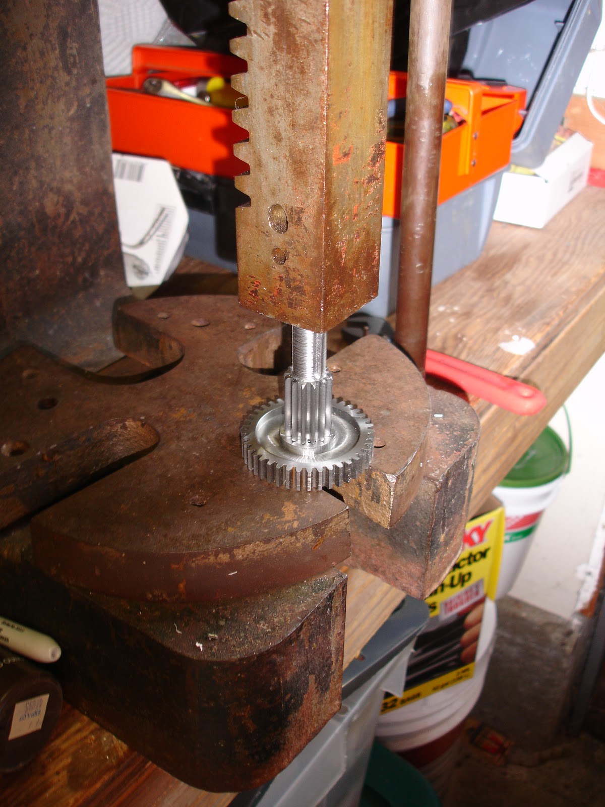
 Every project needs the arbor press. The gears had a 0.001" press fit along with the triple keys. I figured this would be pretty much indestructible.


The final product looks pretty clean. I'll test it in the next few weeks. Hopefully it performs the way it looks!

Sunday, August 23, 2009

Gear Cutting

I decided to be cheap and make ALL of the transmission's gears myself. I'd machined a few gears in the past, but I figured I had more patience than before so it wouldn't be too bad. I started off by turning a "blank" for the gear. This was just a cylinder of the gear's outside diameter. Then I had to machine the teeth into the blank. This is the nasty part. There are a set of cutters meant for involute spur gears. There are 8 cutters required to cut any number of teeth for a particular tooth size. Each cutter has a range of teeth that it can cut. This is because of the gear's tooth profile. A standard gear has what is called an involute curved tooth. This curve is essentially the path taken by the end of a string that is unwound from a spool of thread. Gear teeth require this shape for their teeth in order to have a smooth and constant rotation rate.
Cutting the teeth requires a rotary table or spin indexer and one of the involute gear cutters.


The gears came out looking pretty nice. I'm a bit concerned for the 13 tooth gear. The involute gear cutters don't cut prefect profiles for all the numbers of teeth. 13 tooth gears have the worst profile. It should work in the transmission, but it will probably sound terrible.

Sunday, August 9, 2009

Prototype Transmission

I wanted to come up with a new shifting transmission for my high school's robotics team. The transmission's became my little project every year, and I wanted to see how compact I could make the transmission. My only limiting criteria was that I could make every part. The older 2 speed transmissions required plates larger than my CNC's table travel. My intent was to shrink the entire transmission so the plates could be made on my CNC. This was a lot more of a challenge than I had expected. I came up with the smallest possible configuration possible that produced the gear ratios required for the robot. After that I designed the transmission within a few hours in SolidWorks.
I made blanks for the axles and gears in late June. Then I was busy and couldn't work on anything for the remainder of the summer. Therefore most of the work was done in the week before school started.

The transmission plates came out quickly, although one plate was trashed because the CNC's Y Axis glitched again. I ran out of delrin and was forced to make the second plate from polycarbonate.


Hopefully the rest of the parts come out as quickly as these.