I needed a new hobby. I just don't have the resources to do the kinds of machining projects I have been doing in the past. I kept seeing a really cool concept pop up on various sites: FPV racing. Basically people are building mini quadrotors (5" diameter propellers) and flying through various found obstacles (forests, abandoned buildings, playgrounds, etc...) or purpose built race courses with gates to fly through. Each racing quad had a small analog video camera and video transmitter. This sends low latency video back to the pilot. The pilot wears video goggles so it feels like sitting in the racing quad.
After watching some videos I knew I had to build one and get into this hobby. There are tons of tutorials online suggesting which parts to get to build one. I figured since I had 0 experience with FPV racing I would go with standard parts and make my own custom one after learning more.
A week after deciding I was getting into the hobby I had this show up at my door! I pretty much went with the standard parts from Lumenier. This wasn't the cheapest option, but I knew the parts were decent and would work together.
The frame was much higher quality than I had expected. The edge surface finish and dimensions were all perfect. I hadn't worked with much carbon fiber before this, so I finally got a chance to feel just how good carbon fiber's stiffness to weight ratio was.
Here's all of the power wiring. There's a nice power distribution board I could use to connect the ESCs. There are also LED boards that let me keep track of the quadrotor when flying without the FPV goggles.
I made mounts for all of the electronics using 3d printed parts. This was much cleaner looking than the usual hot-glue and tape techniques used in all of the tutorials I saw for building this type of quadrotor.
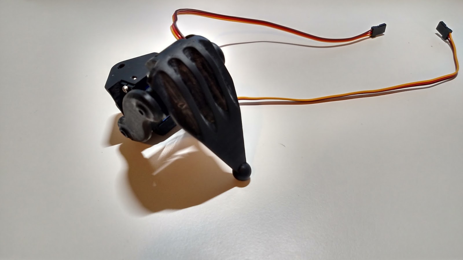
Here's the final assembly. It looked super clean and was ready for a first flight. The radio mount was pretty heavy, but I needed something to protect it. I also didn't have enough room inside the frame to hold it.
I quickly discovered that my camera needed to be tipped upwards. When trying to fly quickly the quadrotor tips steeply forward. This means you look more at the ground than what you're flying towards. I could only tip the camera 15 degrees, but this made a huge difference for me.
I also made a carrying case for all of my equipment. I had the case lying around in my apartment, but it needed foam. I bought some furniture foam (bad choice: too squishy and hard to cut) and made cutouts for everything I needed for a day of flying.
I managed to find a local group of other FPV racers and finally had people to compete with. Unfortunately my riskier flying led to some hard crashes. The video transmitter mount was shattered in one impact. I need to get a less brittle material for the mount parts (or just make them harder to directly hit).
I also went through a bunch of propellers. Broken parts start to add up and really increase the cost of the hobby. Thankfully I only broke my 3d printed parts or propellers. The pricey electronics, motors, and frame have all held up well.
I also discovered the original FPV camera had some latency. This made flying very difficult. I opted to buy one of the popular "board" cameras.
The new camera left me with more space inside the frame. I was able to sit the video transmitter under the carbon fiber, so I saved a bunch of weight and made the build look significantly sleeker.
Overall FPV racing has been a fantastic new hobby to get into. It take a fair amount of practice to be competitive with the other racers, but the feeling of flight you get is worth all of the effort. It's like a video game, but much more exciting. Crashing has real consequences (breaking expensive parts), which really gives an adrenaline rush. It's also cool being able to see the real world from a new perspective, something you just can't get in a video game. I still need to get a proper recording camera so I can share my best crashes.
I worked to redesign the hexapod using a more robust set of servos. I concluded plastic gear servos would all fail, so I went with the cheapest full metal gear servos I could find online.
I bought a number of servos to test. Most of the metal gear servos had one plastic gear inside. I could generally strip the single plastic gear after rapidly back driving these servos by hand. I only managed to find one all metal gear servo in the size I wanted. These came out significantly more expensive than the older plastic gear servos at around $8 each. Even with the increased cost, the hexapod is still significantly cheaper than typical kits.
Since I got new servos I had to redesign the legs. The original leg design wasn't very elegant, and it didn't take advantage of my 3d printer enough. I redesigned the legs with a more compact collapsing design. In addition, each leg was designed to be fully modular. This gave me more room for an electronics compartment. I also got black resin for my printer. I figured the parts would look more professional if they weren't clear.
The black resin is very hard to photograph on my white table. The new leg hides the servos much better than the last one. I also through through some of the cable management this time. I even added special conduit in some of the frame parts to keep each wire organized.
I decided to make the main body a single piece. This ended up being my largest print to date. I'm lucky it finished without any major problems. The surface finish on the parts was starting to degrade at this point. I later (after calling Formlabs support) found a single piece of dust on one of the galvo mirrors (the mirrors that sweep the laser to draw the part) will create a very rough and improperly cured surface.
The supports had to extend into the part. this made cleanup a pretty big pain. I integrated all nut holders as well as strengthening ribs into the frame. This part was really complex to draw up. I also made sure to fillet as many corners as possible to reduce the likelihood of shattering the parts.
The first test fit of the parts. It looks like there is a massive amount of room inside the body, however the center hole is the location for the battery and battery cover. I plan to use a small 3 cell (11.1V) LiPo battery. The new body is much shorter than the last hexapod design. The legs also fold up much nicer.
I printed the top cover (raspberry pi mounts to this) and sealed up the body for the first time. I also added some cable sleeves to the servo wires. Unfortunately these are a pretty big pain to deal with. I decided to skip out on them for the final assembly.
I finally ordered all of the servos after finishing the full design and checking to make sure the leg was durable and cleanly implemented. The servos have a blue anodized body. The branding is held on my stickers, so I removed them all to make a very clean looking build.
I also bulk printed the rest of the leg parts. I used a huge amount of printer resin for this project. My desk ended up an unusable mess again...
After too many hours of assembly I finally completed the mechanics. This thing is pretty massive given the size of my printer. I also love how it is radially symmetric on the outside, unlike the last hexapod design.
The legs fold up nicely to make a compact frame. The servo wires are left unshielded, but they don't really detract from the aesthetics and shouldn't have any wear issues from rubbing on joints.
The hexapod gets even bigger when I expand out the legs. It is somewhat hard to make it balance properly without any power on the servos. There is enough gearing to prevent backdriving of the legs if all of the legs are touching the ground.
The ground clearance is pretty large too. The legs have significantly more range than what is shown. I think I will be able to give this some very life-like animation once I get around to finishing the code.
The wiring ended up extremely clean. Each servo driver board could handle 16 servos. I only had 18 total, so I split the servos evenly between the two driver boards. This is one of my first projects where I attempted to design for cable management. It really paid off and made the overall build much cleaner.
I still haven't purchased any batteries for the hexapod, so I run it from a 12V power supply. Everything is controlled and programmed over wifi because the hexpod runs on a raspberry pi. I simply SSH into the os and run everything from the command line. Eventually when I finish the code I'll add in joystick control, but for now I can just enter simple commands.
Calibration of the legs and most of the testing was done upside down. This prevented the same disaster I had before with the improper walking algorithm. Slamming the entire body weight on one servo due to bad code might break a servo or leg joint. The body weighs enough that it doesn't tip over.
Here is the first test I ran after calibrating all of the leg servos. I found the end points for each servos travel and matched them between all of the legs. The code now knows the angle a leg points when given a particular PWM signal to a servo. Not every servo responded the same, so I had to do each joint individually. This video shows the full range of each joint.
The first (and only) walking test I made was a turn in place. My inverse kinematic models seem to work. I will need to make a generalized walking algorithm in the future.
Overall the new mechanics are leagues ahead of the old design. The newer servos are much more powerful and durable than the old ones, which really justifies the slightly higher cost. I told myself I wouldn't start any new projects until finishing this one. I guess I'm kind of cheating because I made it walk in a circle and I'm calling it "done". I have plans to create a generalized walking algorithm in the future, one that doesn't have predefined gaits. I want the hexapod to walk more like a living creature than a robot.
It has been a few years since I built my guitar. I've come to be very annoyed with the shape and weight balance of the body. This comes down to two complaints. First I can't sit with the guitar on one leg like any regular guitar, which makes playing it in a relaxing position a very difficult task. Second I can't play with the guitar while standing up and hanging from a strap. The heavy neck and head had shifted the center of gravity fairly far forward. The guitar tended to tip forward even with the extended front strap mount.
After thinking about the problem for some time I figured I needed to look at the center of gravity in relation to the two mounting points for the strap. Looking at it now, the CG is obviously going to pull harder on one end of the strap than the other end when hanging in a comfortable playing position. I concluded I needed to make the CG as close to centered between the two strap mounts as possible. I figured friction between the strap and the players neck could tolerate some unbalanced CG.
I designed a new set of side plates for the guitar. These plates differ from the originals in a few ways. First, they're wider than the original plates. This reduces the contact pressure on your leg when playing. Second, they have a concave shape. This allows me to stably rest the guitar on when leg. The concave shape makes it significantly more comfortable to play for extended periods of time. Third, the new plates have more mass in the back. This shifts the CG further back and helps to mitigate the tipping seen in the old design. Finally, The strap mounting points were shifted to be more centered on the CG. I didn't make it perfectly centered, but the strap should hold some imbalance in the weight by friction on my neck.
I think the new plate design just looks a lot better than the old ones. I had more input from friends on what looks good / bad as well as ways to fix what doesn't look good.
The upgrade parts really did the trick - I can comfortably play the guitar while sitting or standing. There is still a small amount of weight imbalance when playing while standing, but it doesn't prevent me from using the guitar. The old design was mostly impossible to play when standing up. The bigger side plates did add some more mass to the guitar. The old design was about 10.1 pounds, while the new design is around 12.6 pounds. I think I need to make a new guitar from scratch if I want to drop the weight and get the right weight balance. I think the neck and especially the head really mess up the center of gravity because they are the furthest portions from the body. An easy improvement would be changing the fretboard material to something less dense than stainless steel (titanium or aluminum). Overall I'm pretty happy with the guitar in its current state, and I probably won't get or build a new one for quite a while.
I finally needed to print a functional gear. Driving my RC car in the snow was a bit too much for the main reduction gear (My 3D printed A-arms seemed to hold up fine this time). Snow got into the gear (due to a very poor design that left the gear exposed) and was turned to ice by compression from the pinion gear. The built up ice seemed to push the motor out of the correct meshing distance. The motor then proceeded to grind away most of the teeth.
The snow was deeper than this in most spots. I took this picture after the car had already stripped the teeth from the main reduction gear.
I put the car in the bathroom to wait for the snow to melt. The electronics avoided the water for the most part, so the only damage done to the car was the stripped gear.
This is the slot in the bottom of the chassis that leaves the gear exposed. The replacement gear is already in the car at this point. I managed to get a face full of gear teeth after a second or two of run time. I didn't have the car on the ground, so the forces on the gear teeth shouldn't have been too high. The gear teeth seem to have shattered. I think this is due to warpage in the gear after it originally printed. The portion of the gear teeth touching the support material had significant warpage. I found this was a problem in my early gear tests, but I decided to try running the gear anyways. I increased the spacing between the pinion and the reduction gear to compensate for the wapage and prevent binding. I also post-cured the gear, which increases the strength and hardness. The post-cure also made the gear more brittle which would explain the shattered teeth.
It's hard to get a good image of the gear without removing it from the car which takes a while. I didn't want to take apart the car until I had a suitable replacement ready to test.
I tried printing with my black resin instead of the clear resin. I had hoped the black resin would have less warpage than the clear resin.
The gear in the bottom left is the original gear. The bottom right is my new replacement gear printed in the black resin. The top two gears are spares that I printed, but didn't release from the support material.
I used a machinists square to visualize the warpage on the gear teeth. The majority of the gear has gear teeth that are square to the faces of the gear, however a small portion (~20%) has slanted teeth like these. This makes it impossible to have a proper gear spacing without binding. I will keep trying different orientations and possibly different gear geometry to avoid this waparge, but for now I may have to order a replacement set of gears for my RC Car.
The output wire from my laptop charger frayed and shorted about a year ago. The wire was built into the charger and broke right where it came out of the charger. I couldn't do without my laptop so I had to get a new charger. I kept the broken one so I could repair it and have a spare at some point. There wasn't enough wire left out of the charger to simply solder the cable back together, so I knew it would need a full case replacement. I also wanted to add a second connector so I could remove the output cable and a similar break in the future.
The charger appeared to be one solid piece of plastic. There were no seams or obvious places to try prying the charger apart. I managed to chip away the rubber that sealed the output cable to the charger. The small opening let me look inside and determine the wall thickness of the charger's case. I could also see the orientation of some of the internal components. I guessed the circuit board was inserted right-side-up into the charger during assembly which led me to guess which side was the lid.
I used a mill to cut away just the outer wall of the charger. I stepped down a small amount with each pass until the top lid broke free. It turned out to be held in with plastic snaps. I believe the lid was glued or friction welded to the rest of the case. It was a clean, but unrepairable design. I managed to avoid cutting any of the components.
The charger had pretty simple internal geometry. I reversed engineered the critical geometry in the case to hold the remaining components.
I bought a pretty nice looking connector without looking at the dimensions... The connector wasn't going to fit in the original case geometry, so I was forced to put it on the lid. I'll admit its a strange form for a charger, but it worked out. I originally planed to use the black resin on my 3D printer to make it look nice, but I got lazy and used the clear resin that was already in my printer.
Here is the main part of the case after it came out of the 3D printer. This is probably the largest part I've printed so far. Thankfully it didn't have a print failure like I had with a few other parts recently.
The lid also printed cleanly. As usual the extra material for the support felt like a waste, but there isn't much I can do to avoid adding it.
I wanted the charger to be symmetrical, so I put screws on the bottom. They don't hold anything together, but they do look nice.
The charger fit snugly into the case. The wall power plug even fit into the case!
Here's the lid before squishing the remaining wires into the charger.
The charger has been revived! The design is pretty strange, but it's functional which is what counts. The upward angle output plug is actually nice because it reduces wire stress when reaching from the floor to a table. It also makes the USB charging port easier to access. I should have been less lazy and printed the charger case in black, but at least the insides are visible like one of the old clear gameboys.
This time the rear A-arms on the RC car broke. I may no longer have access to a milling machine, but now I have a 3D printer. I modified the CAD for the front A-arms and had a set of rear A-arms printing in a few hours. These parts took a mere 5 hours to print. They could have taken less time, but I decided to try printing with the high layer resolution setting (0.025mm per layer). I also tried printing the parts directly on the table. Technically this is frowned upon with this printer, but the parts came out mostly fine. It saved a ton of support material, so I can live with any defects caused by printing directly on the table.
The car looks pretty slick with all these custom parts!
I also added the shock spring mounts. These prevent any binding between the shock and the replacement A-arms.
Unfortunately... I went too hard with the car shortly after making the new parts...
My replacement shock spring mounts took up more space than the originals. This prevented the shock from reaching its end stopper. The end stopper is an internal piece of rubber that prevents the piston from bottoming out and smashing into hard plastic. The car hit a hard landing after a jump and slammed hard plastic into hard plastic. The 3D printer parts can be post cured (which I did). The post curing greatly hardens the plastic, but also makes it more brittle. I won't do that with a future set of A-arms.
I'm starting to learn the material limitations from the 3D printer. The resin cures to be a somewhat brittle plastic. I have been post curing all of my parts (exposing them to additional UV) to make them harder. The parts that come out of the machine can be somewhat flexible and have a soft surface. The gears I've made need to be hardened or they will wear out quickly. This application of the plastic is better soft and slightly weaker. The added flexibility lowers the forces on the parts and prevents shock loading. I'll also look into making certain portions of the A-arm thicker. Holes - especially tapped holes become stress concentrators. These create points where a crack can propagate and make the part considerably weaker.