I worked to redesign the hexapod using a more robust set of servos. I concluded plastic gear servos would all fail, so I went with the cheapest full metal gear servos I could find online.
I bought a number of servos to test. Most of the metal gear servos had one plastic gear inside. I could generally strip the single plastic gear after rapidly back driving these servos by hand. I only managed to find one all metal gear servo in the size I wanted. These came out significantly more expensive than the older plastic gear servos at around $8 each. Even with the increased cost, the hexapod is still significantly cheaper than typical kits.
Since I got new servos I had to redesign the legs. The original leg design wasn't very elegant, and it didn't take advantage of my 3d printer enough. I redesigned the legs with a more compact collapsing design. In addition, each leg was designed to be fully modular. This gave me more room for an electronics compartment. I also got black resin for my printer. I figured the parts would look more professional if they weren't clear.
The black resin is very hard to photograph on my white table. The new leg hides the servos much better than the last one. I also through through some of the cable management this time. I even added special conduit in some of the frame parts to keep each wire organized.
I decided to make the main body a single piece. This ended up being my largest print to date. I'm lucky it finished without any major problems. The surface finish on the parts was starting to degrade at this point. I later (after calling Formlabs support) found a single piece of dust on one of the galvo mirrors (the mirrors that sweep the laser to draw the part) will create a very rough and improperly cured surface.
The supports had to extend into the part. this made cleanup a pretty big pain. I integrated all nut holders as well as strengthening ribs into the frame. This part was really complex to draw up. I also made sure to fillet as many corners as possible to reduce the likelihood of shattering the parts.
The first test fit of the parts. It looks like there is a massive amount of room inside the body, however the center hole is the location for the battery and battery cover. I plan to use a small 3 cell (11.1V) LiPo battery. The new body is much shorter than the last hexapod design. The legs also fold up much nicer.
I printed the top cover (raspberry pi mounts to this) and sealed up the body for the first time. I also added some cable sleeves to the servo wires. Unfortunately these are a pretty big pain to deal with. I decided to skip out on them for the final assembly.
I finally ordered all of the servos after finishing the full design and checking to make sure the leg was durable and cleanly implemented. The servos have a blue anodized body. The branding is held on my stickers, so I removed them all to make a very clean looking build.
I also bulk printed the rest of the leg parts. I used a huge amount of printer resin for this project. My desk ended up an unusable mess again...
After too many hours of assembly I finally completed the mechanics. This thing is pretty massive given the size of my printer. I also love how it is radially symmetric on the outside, unlike the last hexapod design.
The legs fold up nicely to make a compact frame. The servo wires are left unshielded, but they don't really detract from the aesthetics and shouldn't have any wear issues from rubbing on joints.
The hexapod gets even bigger when I expand out the legs. It is somewhat hard to make it balance properly without any power on the servos. There is enough gearing to prevent backdriving of the legs if all of the legs are touching the ground.
The ground clearance is pretty large too. The legs have significantly more range than what is shown. I think I will be able to give this some very life-like animation once I get around to finishing the code.
The wiring ended up extremely clean. Each servo driver board could handle 16 servos. I only had 18 total, so I split the servos evenly between the two driver boards. This is one of my first projects where I attempted to design for cable management. It really paid off and made the overall build much cleaner.
I still haven't purchased any batteries for the hexapod, so I run it from a 12V power supply. Everything is controlled and programmed over wifi because the hexpod runs on a raspberry pi. I simply SSH into the os and run everything from the command line. Eventually when I finish the code I'll add in joystick control, but for now I can just enter simple commands.
Calibration of the legs and most of the testing was done upside down. This prevented the same disaster I had before with the improper walking algorithm. Slamming the entire body weight on one servo due to bad code might break a servo or leg joint. The body weighs enough that it doesn't tip over.
Here is the first test I ran after calibrating all of the leg servos. I found the end points for each servos travel and matched them between all of the legs. The code now knows the angle a leg points when given a particular PWM signal to a servo. Not every servo responded the same, so I had to do each joint individually. This video shows the full range of each joint.
The first (and only) walking test I made was a turn in place. My inverse kinematic models seem to work. I will need to make a generalized walking algorithm in the future.
Overall the new mechanics are leagues ahead of the old design. The newer servos are much more powerful and durable than the old ones, which really justifies the slightly higher cost. I told myself I wouldn't start any new projects until finishing this one. I guess I'm kind of cheating because I made it walk in a circle and I'm calling it "done". I have plans to create a generalized walking algorithm in the future, one that doesn't have predefined gaits. I want the hexapod to walk more like a living creature than a robot.
I've always wanted to build a Hexapod. They look pretty cool with all of the legs moving in sync. They can also be used as a desktop toy, unlike my RC car, which is basically an outside only toy. The biggest problem with hexapods is they are really expensive. A proper hexapod requires three degrees of freedom for each leg. This ensures that the leg doesn't need to slide on the ground. The three degrees of freedom per leg and six legs require a hexapod to have at least 18 servos. The servo cost adds up fast and had previously discouraged me from building a hexapod. Recently I came across micro sized servos (HXT900 9g servos). These servos cost about three dollars each. Even with 18 servos that still isn't too expensive compared to typical on brand servos that cost about 20 dollars each.
I wanted to build the hexapod around my new 3D printer. The first thing I decided to do was integrate the servo splines into the legs themselves. After a number of test prints I was able to confirm it is possible to create micro size servo splines with my 3D printer (Form1+). I also wanted to keep the design minimalistic and avoid over complicated joints and leg segments.
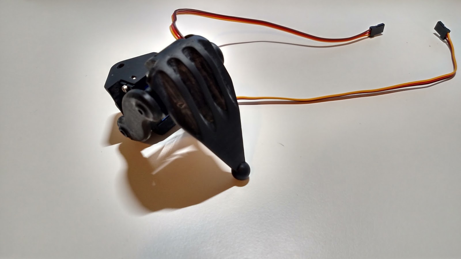
I bought three servos before I committed to building the hexapod. I printed and assembled one leg to ensure the servos would be strong enough to drive the leg. I also wanted to test the tolerances on the servo splines with multiple servos. This image shows the leg prototype, The only change I made to the leg design was an increase in the depth of my logo.
This was the first "production" run for my 3D printer. I had to make six copies of each leg part as well as the body section. Aside from one print failure (on the main body servo mount plate) everything printed perfectly. I literally couldn't make these parts through machining given the orientations of the splines and the shapes of the parts.
This is the body piece ( the one that printed correctly) as it came off of the printer. There was an update to the printer software that dramatically reduced the material wasted in the support structure for the parts.
Here is the part before support material removal. The supports are removed with wire cutters and then the remaining bumps on the part surface are removed with a file.
The final part looks pretty clean. All of the dimensions seem to be within tolerance for the hexapod. There is some warpage in the part that occurred after the post curing, but it shouldn't prevent the part from being usable.
Each servo requires two 2-56 screws to be threaded into the frame. My hand got pretty tired trying to screw all of the servos into the mounting plate. Each servo fit nicely into the plate.
I decided to try fitting all of the pivots into the lower central support plate. It was fun getting to see the hexapod come together.
This was the first time the hexapod was fully assembled. I knew the wiring would be an issue, but I didn't realize how messy the hexapod would look without proper wire management.
Here is my programming testing setup. I was at my house for the winter break and no longer had access to my 3D printer. I had CNC access but I didn't particularly want to get covered in chips as I usually do when machining. I used a raspberry pi model a+ as the controller. This raspberry pi is the smallest one currently available. I wanted to run the hexpod with linux and python because it makes the programming easier. The hexpod currently connects to a computer over wifi which was really easy to do and should be a convenient way to control the hexapod. The two blue boards are PWM driver boards from adafruit. Each board can drive up to 16 servos ( I needed to drive 18 so I had to get the second board). The boards are controlled with an I2C interface. This means I need a minimal number of pins from the raspberry pi to control all of the servos. It helps to keep the wiring from being a mess.
Here is an early motion test. I programmed the legs to look like they were walking. I still needed to calibrate each servo and complete the actual leg motion program. This shows the hexapod moving its legs near the peak servo speed.
This was the first PCB I milled on a proper milling machine. I've always had access to a dedicated PCB mill, so coming up with my own milling procedure was fun. I drew the circuit board in SolidWorks so it would be easy to generate the G-Code for the CNC. A proper circuit CAD program like eagle probably would have been a better choice.
The PCB I milled was for the hexapod's power supply. This supply is capable of driving up to 20A at 5.5V. I wanted to drive the hexapod with a 7V battery, but the servos and raspberry pi wanted 5V. Each servo doesn't draw very much current, however the combination of all 18 which could all be running at full torque at one time would overwhelm most power supplies. I decided to go with the 20A supply to ensure there would never be a sever voltage drop that could shut down the raspberry pi.
Here is the final hexapod assembly. I ended up milling three plates from polycarbonate to create the electronics mount. The electronics are all held in with zip ties. I would have used screws, but I didn't want to make the standoffs required to mount the electronics with screws.
Unfortunately during testing I managed to break three servos. Shipping the hexapod back from break caused another four servos to die. All of the servos broke at the same internal gear. I haven't been able to finalize testing my leg motion code without a fully functioning set of legs . I chose not to use an existing set of code for the legs because I was excited to create my own algorithm from scratch. I need to rethink my servo choice and look into getting slightly more robust servos. Currently I am looking at using metal gear servos that are around five dollars each. I'm sure the hexapod will be up and running quickly once the new servos are integrated into the design.