I know significantly more about circuit design, microprocessor programming, and signal processing than I did 8 years ago (thanks engineering degree) and wanted to go digital instead of analog. I noticed over the last few years the WS2812b individually addressable RGB LED has become the go-to for cool LED projects. The LEDs typically come soldered to flexible strips which can be cut to length. RGB data is passed from LED to LED, so the number of LEDs driven by one microprocessor can be huge.

My initial plan was to just remake my original underglow setup with a few strips of the WS2812b LEDs, however I figured that wouldn't take advantage of the LEDs being individually addressable. In the middle of thinking about what to build I found a plugin for my computer's keyboard (it has individually addressable LEDs in the keys) that made the keyboard a music visualizer. It displays the frequency components of the music. With the new inspiration I started to look at "going big or going home" for the new music visualizer.
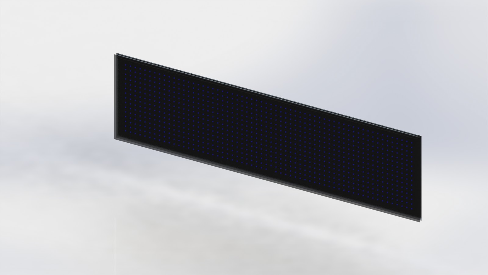
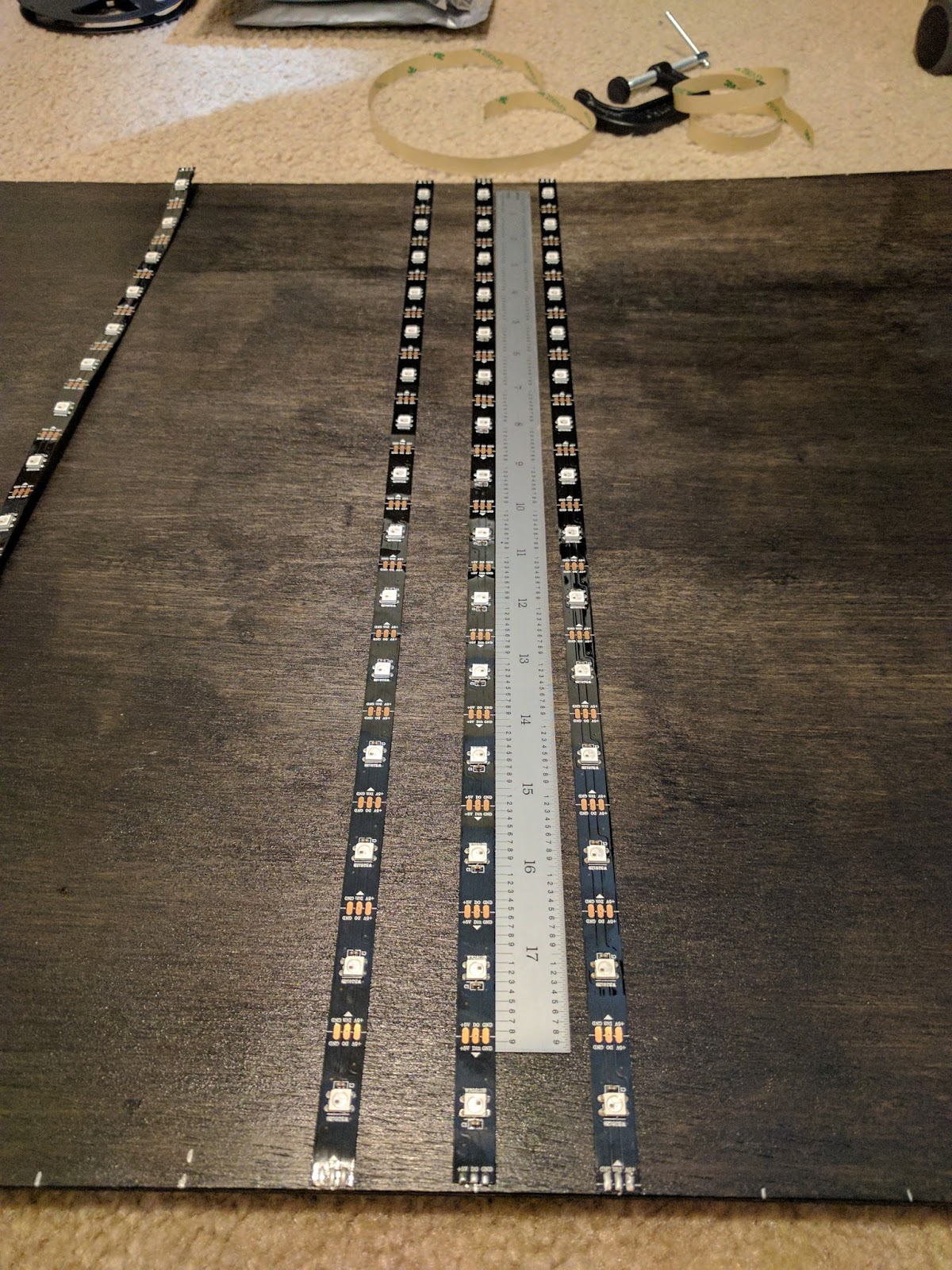
I started with some blue tape and a tape measure and started figuring out how big my wall mounted visualizer would need to be. As usual the size kept creeping up until I settled on an aspect ratio of 4:1 (left and right speakers each get their own visualizer channel with a 2:1 aspect ratio). To make the visualizer match with my computer setup it needed to be as wide as my monitors (all 3 of them) and the speakers. I ended up with a display area that is 2m wide and 0.5m tall. Strips with various LED densities can be found cheaply on ebay. I decided on the 30 LEDs per meter density. The strips are sold in 5m rolls. I discovered that the rolls were actually made from soldered together 0.5m long segments (no cutting or splicing required if the strips are only 0.5m long). The visualizer would be 15 LEDs tall, and 60 LEDs wide. This also works out to an even number of 6 rolls.

Now with the general concept for the visualizer I had to start working out the details. This is also where the numbers got a bit scary for me. Each LED is small and doesn't put out an enormous amount of light. At full brightness on each channel (full bright white light) one of the WS2812b LEDs draws about 60mA at 5V. Easy right? Well... I have a grid of 900 LEDs... A little math now tells me my peak current is more than 50A. That's a lot of current. It's also at 5V, so now I need to worry about voltage drops which could cause LEDs to be dimmer than expected. This means I need to more or less run each strip in parallel with a massive 5V power supply (another quality ebay find).
The 900 LEDs also puts a strain on the processor. The signal requires accurate timing of the high frequency pulses used to transmit the RGB brightness for each LED. I originally looked at using an Arduino since there are nice libraries for driving the WS2812b LEDs already written, but I concluded the Arduino just didn't have enough juice to drive that many LEDs and deal with running an FFT on two channels of audio. Then I came across the Teensy. This uses a significantly more juiced up processor than a typical Arduino. In addition, it has tons of hardware that can lift the difficulty of driving the LEDs from the actual processor. There was a prebuilt library (and breakout board) for the teensy to drive 8 strips of WS2812b LEDs in parallel using the processors DMA (direct memory access) and hardware PWM modules. I also found prebuilt libraries for sampling the audio and running FFTs on the data. These libraries also took advantage of the hardware built into the Teensy's chip to reduce the load and allow more things to be done in parallel on the processor.
One more challenge to add to the project... I had to make everything with hand tools (drill, jigsaw, file, etc...). I don't currently have any machine shop access, so I had to go manual on this. I ended up settling on a wooden frame instead of my typical metal construction. Wood ended up being cheaper than metal, easier to source than metal, and easier to work with than metal.


I still have a few minor details left to complete the visualizer. I still need to add a diffuser to the board, so the led strips and wires are completely hidden. I also need to cover the power supply and other electronics so there is no way to touch the live lines from the wall power. Eventually I'm going to add some bonus features like games on the board (4 player Tetris, snake, pong, helicopter, Pacman, etc..). Since it's so easy to reprogram the processor I can also add new and more interesting visualizers as well.
This might be my favorite project so far. It wasn't the most work or the most complicated. It isn't the highest power output or the most dangerous. However, it is the most aesthetically pleasing. Sometimes I just want to see music and this is a great way to relax and enjoy another aspect of my favorite songs. I might also have to pick up DJing in my free time to share the fun!
Hi,
ReplyDeletewhat components do you use. I want to build the project too.
Thank you.
Andreas
Have you published your code anywhere so i can have a look? would love to make this. thank you.
ReplyDeleteI'd love to see the code or a list of all the libraries used.
ReplyDelete