Well I started the case in August... Now its January...
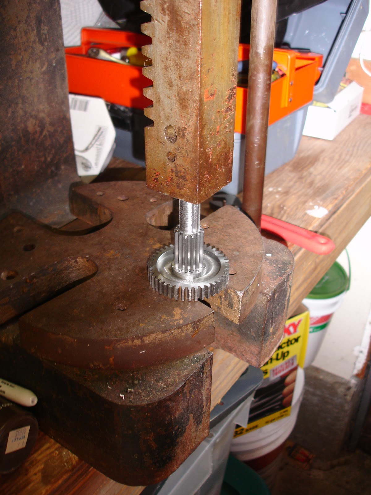
I was a bit of a klutz and in the middle of a bit change from the drill bit for a #2 screw through hole to an 1/8" mill bit I didn't realize that the screw on my CNC's drawbar had backed out. My CNC has a somewhat unique drawbar design that requires a spanner to tighten the collets in place. The collets are really small, only around a 1/2" at their largest dimension. I did some research one time and found out what they were, but I can't remember what they are. I vaguely remember them as ww collets, but I could be completely wrong. In any case my collets use outside threads. When the screw loosened on the drawbar it bottomed out on the collets threads. I didn't realize this and continued to turn the drawbar to tighten the mill bit into the spindle. Sadly the tiny amount of torque I put on the machine was enough to shear the 1/32" pin that slips into the collet's keyway. The collet became stuck in the spindle and the mill bit wouldn't hold in. I had to leave for school, so any machining in the Secret Underwater Base / Machine Shop had to be put off until December.
Surviving a semester of school took its toll on me and left me sleeping a lot over break. Therefore I didn't work on all of the projects I wanted to finish. The phone case turned out to take 3 days. I got lazy again and machined the center ring that surrounds the phone from polycarbonate. In my opinion it looks better than the aluminum anyways.
This was the cursed part that I broke my spindle while making. Once I had my new spindle (which I got repaired and the bearings replaced for free) the part came out pretty quickly. I did discover that my mill bits were all fairly dull. I'll have to order a few more. Thankfully 1/8" mill bits are pretty cheap.
The case turned out exactly as awesome as I had imagined. It does have a few drawbacks...
-It is really heavy. I don't particularly mind, but I really doubt there are many other people that would want a phone that weighs as much as this one.
-It is really huge. This thing rivals a brick... enough said.
-It is sharp. I had to use cap head screws because the hex set I carry around doesn't have a key small enough to tighten a button head screw. So far I only cut my leg once. I attempted to climb over something and one of the screws dug into my leg. If I get cut again I'll replace the cap head screws with button heads.
-It needs a hex set. I'm screwed (hahaha its a pun) if I ever need to remove the battery and I don't have my hex set with me.
It may have a few drawbacks, but I love the case and will probably leave it on the phone until I replace the phone.