Showing posts with label LED. Show all posts

Friday, June 2, 2017

New Project (Finished too) - LED Music Visualizer

I had built underglow for my computer that was reactive to music about 8 years ago. The system had a number of blue LEDs and would vary the brightness based on the overall volume of the music. I had a low-pass filter integrated into the circuit to make it react preferentially to bass. Unfortunately it has been gracefully failing over the last year to the point where it slowly grows brighter until the LEDs are full brightness all the time. I figured it was time to upgrade to something new and improved and started brainstorming ideas on how to build a new system.

I know significantly more about circuit design, microprocessor programming, and signal processing than I did 8 years ago (thanks engineering degree) and wanted to go digital instead of analog. I noticed over the last few years the WS2812b individually addressable RGB LED has become the go-to for cool LED projects. The LEDs typically come soldered to flexible strips which can be cut to length. RGB data is passed from LED to LED, so the number of LEDs driven by one microprocessor can be huge.


My initial plan was to just remake my original underglow setup with a few strips of the WS2812b LEDs, however I figured that wouldn't take advantage of the LEDs being individually addressable. In the middle of thinking about what to build I found a plugin for my computer's keyboard (it has individually addressable LEDs in the keys) that made the keyboard a music visualizer. It displays the frequency components of the music. With the new inspiration I started to look at "going big or going home" for the new music visualizer.

I started with some blue tape and a tape measure and started figuring out how big my wall mounted visualizer would need to be. As usual the size kept creeping up until I settled on an aspect ratio of 4:1 (left and right speakers each get their own visualizer channel with a 2:1 aspect ratio). To make the visualizer match with my computer setup it needed to be as wide as my monitors (all 3 of them) and the speakers. I ended up with a display area that is 2m wide and 0.5m tall. Strips with various LED densities can be found cheaply on ebay. I decided on the 30 LEDs per meter density. The strips are sold in 5m rolls. I discovered that the rolls were actually made from soldered together 0.5m long segments (no cutting or splicing required if the strips are only 0.5m long). The visualizer would be 15 LEDs tall, and 60 LEDs wide. This also works out to an even number of 6 rolls.

My blue tape outline for the visualizer above my desk. this is where I first realized how big this project was going to become.

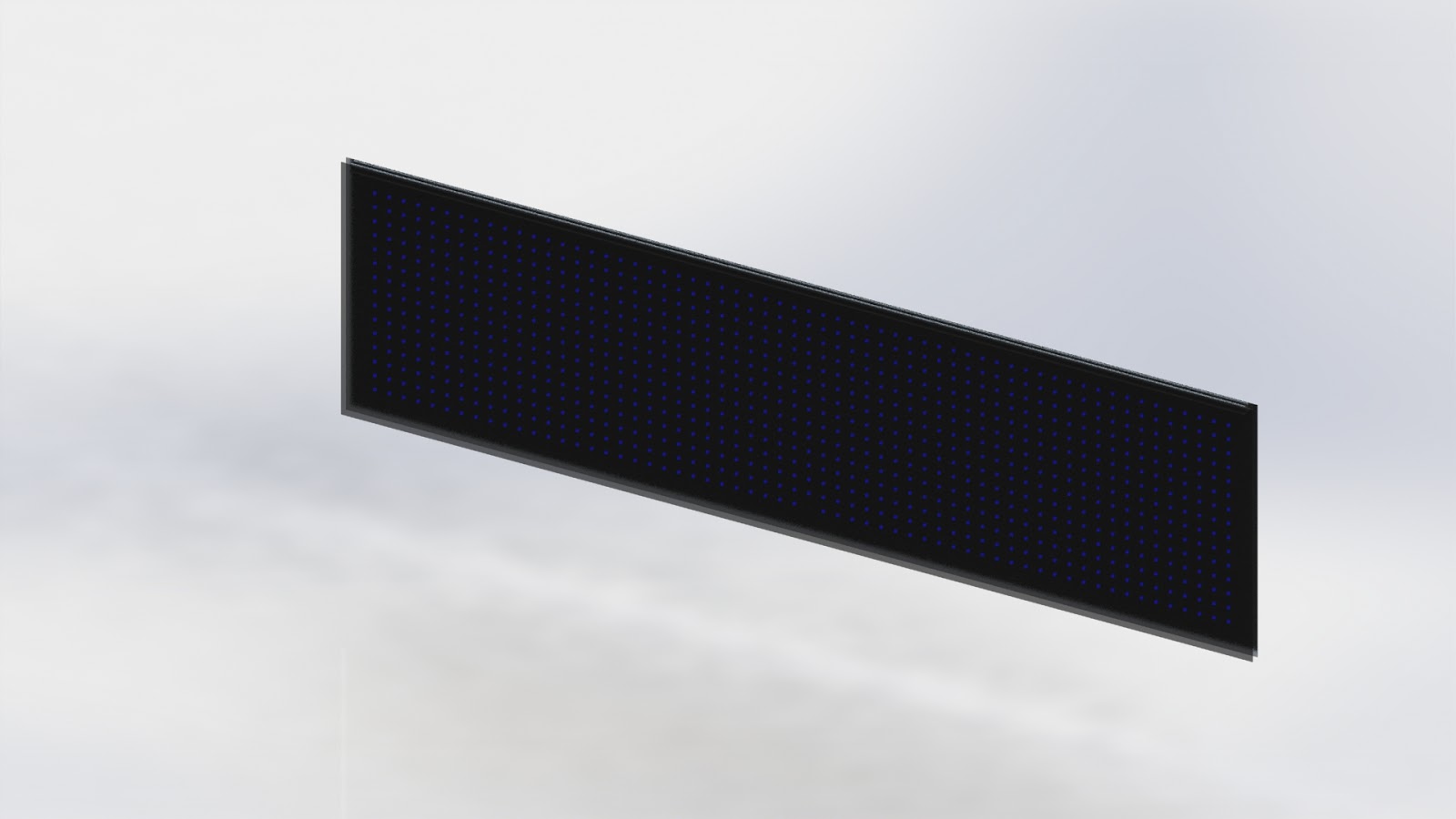
I also tried to render a basic visualizer design to see how the grid spacing would look.

Now with the general concept for the visualizer I had to start working out the details. This is also where the numbers got a bit scary for me. Each LED is small and doesn't put out an enormous amount of light. At full brightness on each channel (full bright white light) one of the WS2812b LEDs draws about 60mA at 5V. Easy right? Well... I have a grid of 900 LEDs... A little math now tells me my peak current is more than 50A. That's a lot of current. It's also at 5V, so now I need to worry about voltage drops which could cause LEDs to be dimmer than expected. This means I need to more or less run each strip in parallel with a massive 5V power supply (another quality ebay find).

The 900 LEDs also puts a strain on the processor. The signal requires accurate timing of the high frequency pulses used to transmit the RGB brightness for each LED. I originally looked at using an Arduino since there are nice libraries for driving the WS2812b LEDs already written, but I concluded the Arduino just didn't have enough juice to drive that many LEDs and deal with running an FFT on two channels of audio. Then I came across the Teensy. This uses a significantly more juiced up processor than a typical Arduino. In addition, it has tons of hardware that can lift the difficulty of driving the LEDs from the actual processor. There was a prebuilt library (and breakout board) for the teensy to drive 8 strips of WS2812b LEDs in parallel using the processors DMA (direct memory access) and hardware PWM modules. I also found prebuilt libraries for sampling the audio and running FFTs on the data. These libraries also took advantage of the hardware built into the Teensy's chip to reduce the load and allow more things to be done in parallel on the processor.

One more challenge to add to the project... I had to make everything with hand tools (drill, jigsaw, file, etc...). I don't currently have any machine shop access, so I had to go manual on this. I ended up settling on a wooden frame instead of my typical metal construction. Wood ended up being cheaper than metal, easier to source than metal, and easier to work with than metal.

Here's the frame after making all the 45 degree cuts on a chop saw (I managed to find one I could use) I'm not used to making measurements with a tape measure that end up being the final part size.

I laid out the frame on my plywood sheet to check sizing

I was lazy and cut the plywood with a jigsaw in my living room...

The full frame layout including the board for mounting the LED strips

I went with a black stain on the wood. I've never finished wood before, so I ended up doing a pretty poor job. Oh well... live and learn!

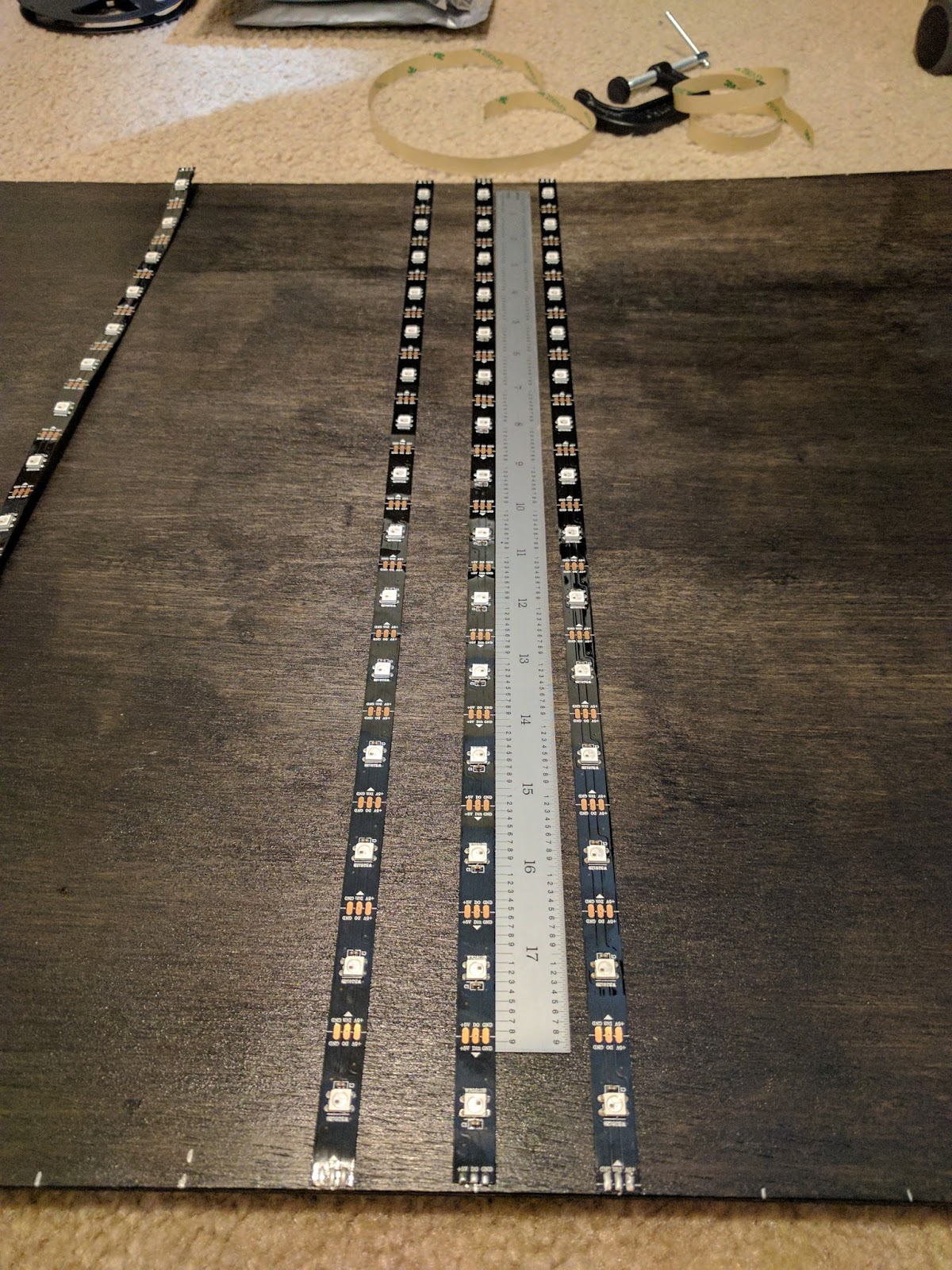
This is after separating half of the strips into their 15 LED (0.5m) segments. Dealing with so many parts is really tedious.

Adhering the strips to the board was extremely time consuming. I tried to make as perfectly square of a grid as possible.

This is right after I finished adhering all the strips down. After a few hours I noticed a number of the strips were starting to peel off the board...

I tried to use gaffers tape to hold the LEDs down to the board. I figured if it is designed to stick to carpet, it should stick to wood.

I was wrong... Gaffers tape did not stay adhered to the wood. Instead it pulled the strips into a tangled adhesive mess. It took me hours to separate each strip from the adhesive roll. This was after attempting to wire some of the strips, so I had to be extra careful to not tear a solder pad off of the strip. I later determined the stain had significantly roughened the surface of the wood. A little bit of sanding and the panel was super smooth, allowing the adhesive to actually stick.

All of the LEDs remounted and stuck to the freshly sanded board really well. I also added some gaffers tape to the outer segments to make sure a single poorly adhered strip wouldn't cause the array to fail. I also finished the wiring for the strips. Every other strip is fed 5V in parallel from the power supply. Adjacent strips are paired and put in series for power. This is equivalent to driving 30 LED (1m) strips off a single 5V supply. I only used PTFE (Teflon) insulated wire. It doesn't melt during soldering and can handle higher amperage compared to wire with other insulation types. It was also much more annoying to strip compared to the usual types of wire I use.

First time powering any of the LEDs (only one of 8 groups)! The visualizer is wired in groups of 8 strips (6 strips at the very ends). The Teensy drives 8 strips in parallel, so I could make the frame rate significantly faster by dividing the number of LEDs evenly between the channels.

After testing each group of strips individually I mated the LED array with the visualizer frame and wired in the signal wires.

First test with the full grid running! Even without full brightness the array is totally blinding.

This is the sketchy ebay power supply I'm using to power the LEDs. It is rated for 70A. I question this rating given the quality of the soldering and component placement (it looks like a kindergartner assembled it). I'll be sure to lock out the visualizer from running all LEDs white at full brightness in the code. This should give a reasonable factor of safety on top of whatever the power supply was "designed" to do. There was no manual for the supply and the labels etched on the side of the supply had some poor translations. I was very careful to not electrocute myself. I checked isolation of the casing, and DC outputs from the 120V line. Eventually this will be totally enclosed and untouchable.

The final array assembly tilted against the wall (before mounting the power supply and processor).

One of my first tests running the FFT visualizer. I only had one color working at the time. I also hadn't mounted any of the electronics to the frame, so it just sat on the floor

Testing out the full rainbow effect on the visualizer. I set it on top of my speakers and tipped it against the wall. I'll mount it to the wall later (and make it centered on the desk).

I still have a few minor details left to complete the visualizer. I still need to add a diffuser to the board, so the led strips and wires are completely hidden. I also need to cover the power supply and other electronics so there is no way to touch the live lines from the wall power. Eventually I'm going to add some bonus features like games on the board (4 player Tetris, snake, pong, helicopter, Pacman, etc..). Since it's so easy to reprogram the processor I can also add new and more interesting visualizers as well.

This might be my favorite project so far. It wasn't the most work or the most complicated. It isn't the highest power output or the most dangerous. However, it is the most aesthetically pleasing. Sometimes I just want to see music and this is a great way to relax and enjoy another aspect of my favorite songs. I might also have to pick up DJing in my free time to share the fun!

Saturday, November 1, 2014

Quick Project - Evil IronMan

I got invited to a Halloween party about two hours before the party started. The party had a mandatory costume policy. Being an engineer and a new owner of a 3D printer I figured I HAD to 3D print my costume. The first thing that came to mind when thinking of 3D printing and Halloween costumes was an arc reactor. I've seen a bunch made on the internet and even a few for various Halloweens in the past. I remember that I had a box of LEDs. Unfortunately, I discovered that I only had two blue LEDs. Luckily I also had eight red LEDs... so the obvious costume became evil IronMan. I spent about 30 minutes drawing up the part in SolidWorks and then sent it to the printer. The print time was a little under two hours (it's cool to be slightly late to parties). While the part was printing I had to make the wiring.


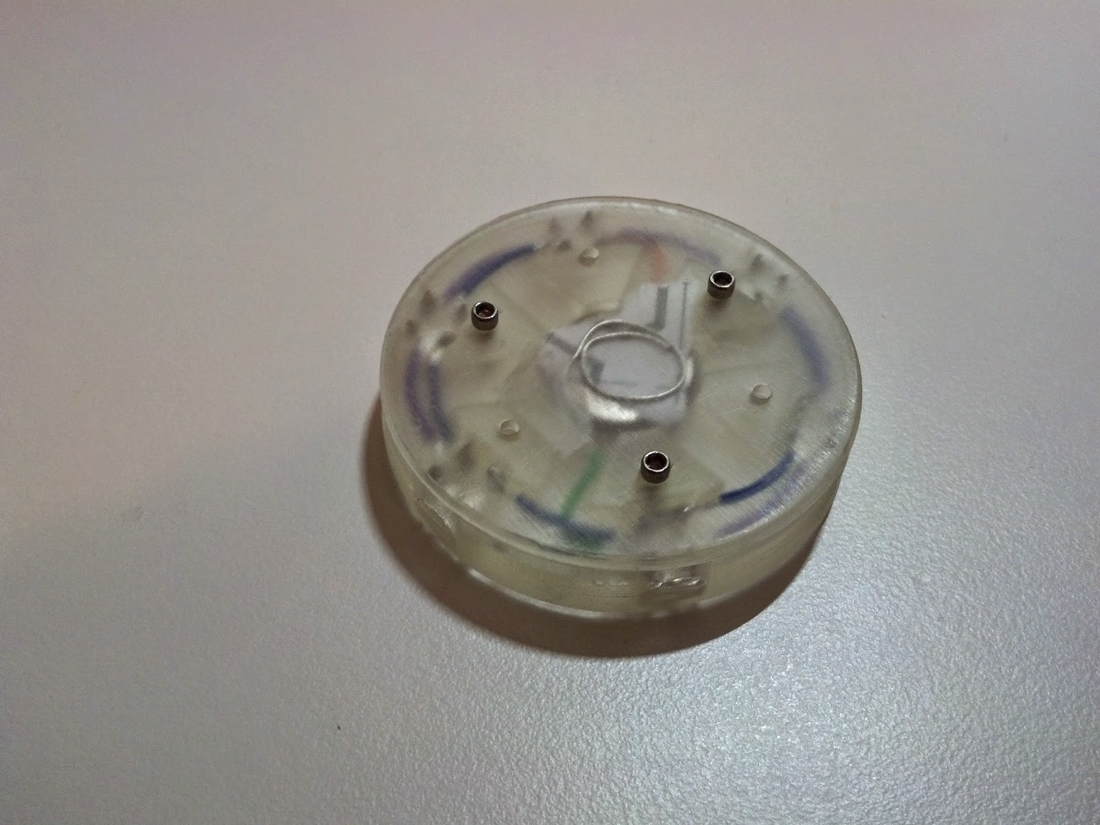
I pushed each of the LEDs through a 1:1 drawing of the frame. I soldered all of the LEDs together with some solid wire to give some structure to the electronics. I also used two bent spiral wires for the + and - connections to the battery. I tore away the paper to release the electronics for the final assembly. I didn't use any current limiting resistors or a proper current driver because the battery voltage was lower than the rated voltage for the LEDs. I also figured that the small coin cell battery wouldn't be able to supply enough current to fry six LEDs in parallel.


Here's a top side view of the arc reactor. Each of the LEDs stuck out from the frame to ensure maximum brightness. It also saved some material and print time.


This is the back side of the arc reactor. I have paper shoved between the battery and the contact to prevent the LEDs from turning on. I didn't have a switch so the back has to be unscrewed to connect and disconnect the battery.


This is the arc reactor shining through my shirt. The camera doesn't do a very good job showing how bright the LEDs looked shining through my shirt. I used lots of tape to hold it in place.

Surprisingly the arc reactor stayed lit up all night. I didn't even have to break out the spare battery and hex key that I kept in my pocket. The design wasn't too great, but im pretty proud of it considering it went from concept to finished product in a little over two hours!

Sunday, June 30, 2013

Desk Lamp FINISHED

Now that it's the summer, I finally had the time to finish the desk lamp. The combat robot destroyed any amount of free time I had. I had been using the lamp without the base for over a semester, while the half finished base just sat on my dorm room floor.

It took a creative setup to machine the other side. I used a 4 jaw chuck from a lathe and clamped it to the mill table. I also added a bolt in the center to hold the part flat to the chuck. The part seems to be flat within .002" which is pretty good because it doesn't matter at all for a desk lamp.


I put some cutting fluid on the part and I used compressed air to keep the chips from clogging up the end mill.


The final base looks perfect!

I snapped a couple photos of the lamp against a whiteboard. It makes a really good background for taking pictures.


I even set it up on my messy desk in my summer apartment.


It definitely goes well with my guitar. I'll need to work on making a desk and other furniture to go with the rest of the things I've been machining lately.

PROS
-The LED is crazy bright. It lights up not just my desk, but also a good fraction of my room.
-MEGA REACH! I can get amazing lighting on any part of my desk.
-Aesthetics. I think this lamp looks amazing.
-Low power consumption. Everyone loves going green now...
-Runs colder. Most desk lamps will give you a nasty burn. This one is pretty warm, but I've held my hand on it without any problems.

CONS
-The ball bearings in the base have too little friction. It swings around on its own on a non-level table.
-Not dimmable. Sometimes its too bright. (I don't think my roommate appreciated it when I pulled all-nighters to finish homework.
-It's fragile. Most of my projects are tough to damage... Not this one.

Overall this is a pretty sweet lamp. A number of people have asked if I am going to make more. I'll probably come up with a production version of the lamp, which gets rid of the CONS and reduces the material and machining costs. There are a few LED desk lamps on the market, but they all suck in my opinion. For now I'll keep using this as my main desk lamp and see how long it lasts (forever hopefully).

Friday, August 31, 2012

Desk Lamp - New Project

During my last semester at school I discovered the need for a desk lamp. The one I used during the semester was chunky and didn't quite have the reach I needed to light the center of my desk (I put the lamp's base on one of my speakers). I also burned myself a few times on the light housing. As usual I figured I could do better.

These were a few of my design thoughts:

-High power LED (More light, less heat, nearly unlimited lifetime, less power consumption, smaller, lighter)
-LARGE (My computer setup is around 80" wide)
-Light weight (The lighter the arm is, the smaller the base can be without the lamp tipping)
-Cool looking (who wants an eye sore on their desk?)

I actually came up with this a few months ago, but I hadn't decided to make it until the past couple days.

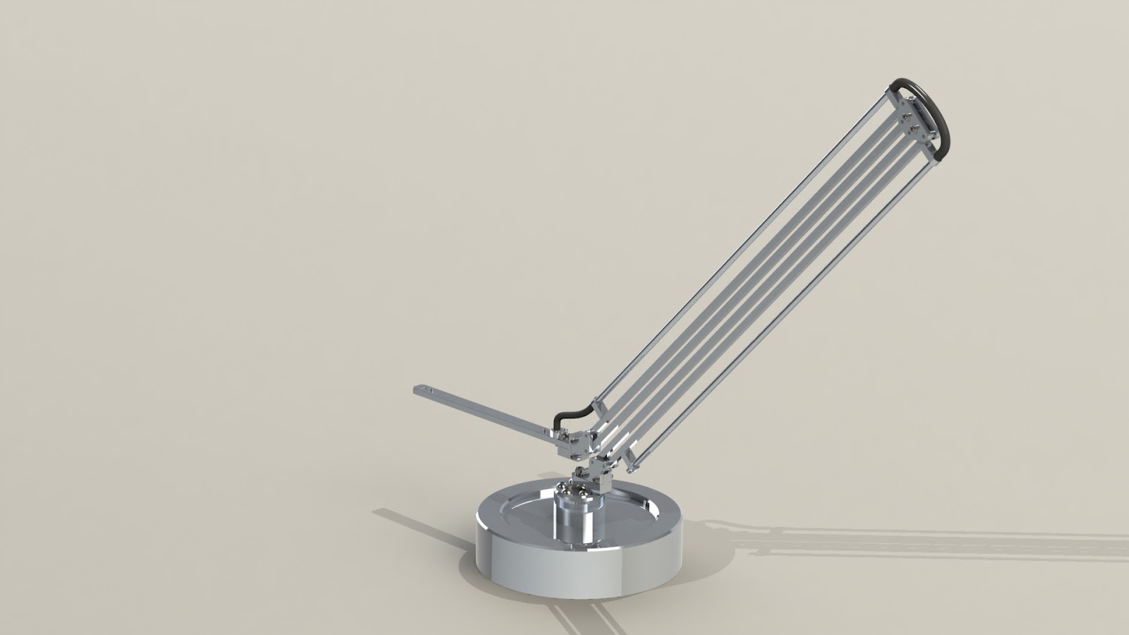
Here's a few quick renders of the lamp in a few positions.


This design has a swivel base to give the lamp more flexibility. The light is held by two parallel arm segments. No matter where the light is positioned it will always be parallel to the base of the lamp. I found a really cool led strip that is a 10 watt LED, so it should easily light up the desk and maybe even the room. I made sure the base was large enough that the lamp would never tip, even when fully extended. The base is an 8" diameter piece of aluminum. The current base will weigh over 9 pounds while the entire arm and light should only weigh a little over a pound.

I started with the arm because the pieces were small and required little material removal. The long pieces used for the parallel arm gave me an excuse to use my 40" calipers (I had been itching to use them to make an actual part).


 These parts could have been made a lot faster if I had a machine that could accept bits larger than 1/8"...
I am fortunate that my CNC mill is very accurate and always seems to hit its dimensions without any need for cutting and measuring, but it's sooooo slow.


All of the arm pieces are made from 1/4" square aluminum. Each one has 1/8" press fit stainless dowel pins.


Each segment of the arm has 1/4" aluminum tubing to keep the wires hidden and protected. The tubing is .035" wall, so it doesn't add much weight at all.


The arm has nearly zero play in the joints. Even the slightest touch to one end will cause the other to move as well. The two end pieces are always perpendicular to each other. It's also symmetrical which makes it harder for me to assemble it incorrectly =D


The arm is held in place by the clamping force from the center joint's plates. This picture also shows the size of the lamp.

So far the lamp seems really solid even though it's made from such tiny aluminum rods. It should be a nice addition to my desk once I finish the base and LED housing.