Showing posts with label Machining. Show all posts

Sunday, August 21, 2016

Mini Combat Robot Finished

I finally found the time and resources to finish the last few parts on the robot. The first and biggest thing was finishing the spinner. I discovered though testing the polyurethane belts I had originally chosen couldn't handle the rotation rate and would stop transmitting any torque (they also melted from slipping). I opted to redesign the spinner using inside-out timing belt. I chose this for a few reasons... I used the timing belt belt inside-out to make sure it could still slip in an impact situation. This prevents the motor from being damaged by the near instant changes in rotation rate. I chose to use timing belt because it's much easier to find small timing belt sizes than it is to find small flat belts. The timing belt also has low stretch cord (fiberglass or kevlar usually) embedded in the belt.

The new timing belt design required the whole spinner be redesigned and made. Thankfully I had a friend with access to a 5 axis CNC. The new spinner is made from a billet of 7075 aluminum (probably not the best choice because it's more brittle than other alloys) with S7 tool steel teeth. I made sure the design could safely handle 30krpm without ejecting the teeth.

I disassembled the whole robot again, and broke it down into just the spinner assembly for testing. I had to do a bit of rework on the main plates to fit the shaft properly. The new spinner mounted properly the first try. I also put some armor surrounding the motor shaft to make sure debris can't damage the motor.

The belt tensioner can be seen on the underside. The original design didn't need one because I was using stretchy polyurethane belt. In this new design, the timing belt is pulled tight by a few ball bearings pressed onto a dowel pin. The dowel pin mount slides back and is locked in place by two screws. The mounting block has a precisely machined slot to keep the bearings perfectly perpendicular to the mount.

Here is a quick test of the spinner mounted to some random material I had laying around. A friend and I threw objects at the spinner to see how much it could damage it could do. The soda can is one of the most satisfying tests.

I also tried throwing 2x4s at the spinner. I wasn't taking video at the time, but the hit that damaged this chunk of wood threw the 2x4 well above my head. I quit testing at that point before I did something dumb(er) and injure myself.

The robot was pretty much done at this point. I just needed to wire everything up and get the top/bottom plates made from metal (I had some temporary laser cut acrylic plates). Unfortunately I couldn't figure out how to get all of the motor controllers and wires to fit. Everything was just too packed in.

I opted to get new motor controllers for the drive. Hobby brushless motor controllers have come a really long way since I bought the ones for the drive. The old ones were rated for 25 amps each. They also couldn't instantly switch from forward to reverse (dumb "feature" for RC cars). The new controllers (the tiny circuit boards in the picture above) are meant for FPV racing multirotors. They're rated for 30 amps and can instantly switch from forward to reverse (an important feature for multirotors that can fly upside down). I've used these controllers on my hexrotor, so I knew they were good and the ratings were not made up.

A quick test of the drive ended up shattering the old 3d printed spline couplers. I reprinted the parts with tough resin (a less brittle type of printer resin from Formlabs). These parts held up fine and are still in use.

I easily fit all of the electronics in the robot. I also finally mounted the power wires in the robot such that the lid could close and seal the battery in.

A quick test fit showed even the battery could fit. I added some pieces of dense/rigid foam in to keep the battery and spinner ESC in place. The foam has some squish, so it prevents the parts from getting too much force during an impact. I also finally got the top and bottom plates made. I gave up trying to get machine access to make the plates myself. I ended up sending them out to a local shop. They even used the material I had already purchased. The parts ended up really cheap. I will definitely send out any future waterjet parts to this shop. It ends up better quality and even cheaper than me paying for my own machine time at a place like the techshop.

The plates fit nicely and none of the electronics or wires are badly squished. It was nice seeing it finally done after starting the project more than 3 years ago.

It makes a really nice display piece of my bookshelf... I  don't have any competitions to go to, so finishing this was mostly just to have closure on the project.

The robot is pretty quick. The new drive ESC make it significantly easier to drive. It rumbles the floor pretty badly, so I probably won't drive this indoors again (don't want to anger the neighbors below).

A few months after actually finishing the robot I finally got a chance to test it on something. A friend had me pickup some Legos from craigslist for him. He didn't pick them up after the entire summer. Normally I'd be down to play with Legos, but these were kinda gross. They were covered in dirt and who knows what else. They took up room in my living room... something had to be done...

My roommate and I made a video to provide some "motivation" for my friend to pickup his Legos. We made a small house using some of the bricks (only the really common or already damaged bricks). The robot instantaneously disassembled the house (ignore my poor driving).


The spinner took a nice chunk out of one of the bricks. The video also worked well. All of the Legos were picked up within a day of posting on Facebook.

It was nice to finally put this project behind me (actually behind me on a bookshelf). I'll probably never have it actually compete at this point. I probably can't even use it to smash stuff since I don't have an arena or some other safe place to protect me from flying pieces. That being said, it makes a nice desk ornament and could be used if I ever have the immediate need for a small combat robot!

Monday, April 27, 2015

Guitar Upgrade Parts

It has been a few years since I built my guitar. I've come to be very annoyed with the shape and weight balance of the body. This comes down to two complaints. First I can't sit with the guitar on one leg like any regular guitar, which makes playing it in a relaxing position a very difficult task. Second I can't play with the guitar while standing up and hanging from a strap. The heavy neck and head had shifted the center of gravity fairly far forward. The guitar tended to tip forward even with the extended front strap mount.

After thinking about the problem for some time I figured I needed to look at the center of gravity in relation to the two mounting points for the strap. Looking at it now, the CG is obviously going to pull harder on one end of the strap than the other end when hanging in a comfortable playing position. I concluded I needed to make the CG as close to centered between the two strap mounts as possible. I figured friction between the strap and the players neck could tolerate some unbalanced CG.

I designed a new set of side plates for the guitar. These plates differ from the originals in a few ways. First, they're wider than the original plates. This reduces the contact pressure on your leg when playing. Second, they have a concave shape. This allows me to stably rest the guitar on when leg. The concave shape makes it significantly more comfortable to play for extended periods of time. Third, the new plates have more mass in the back. This shifts the CG further back and helps to mitigate the tipping seen in the old design. Finally, The strap mounting points were shifted to be more centered on the CG. I didn't make it perfectly centered, but the strap should hold some imbalance in the weight by friction on my neck.

I think the new plate design just looks a lot better than the old ones. I had more input from friends on what looks good / bad as well as ways to fix what doesn't look good.

The upgrade parts really did the trick - I can comfortably play the guitar while sitting or standing. There is still a small amount of weight imbalance when playing while standing, but it doesn't prevent me from using the guitar. The old design was mostly impossible to play when standing up. The bigger side plates did add some more mass to the guitar. The old design was about 10.1 pounds, while the new design is around 12.6 pounds. I think I need to make a new guitar from scratch if I want to drop the weight and get the right weight balance. I think the neck and especially the head really mess up the center of gravity because they are the furthest portions from the body. An easy improvement would be changing the fretboard material to something less dense than stainless steel (titanium or aluminum). Overall I'm pretty happy with the guitar in its current state, and I probably won't get or build a new one for quite a while.

Saturday, November 29, 2014

Mini Combat Robot Update... again

I decided to use my new 3D printer to solve any engineering problems with the mini combat robot. The first problem was making the motor controllers fit in the space I left for them.


Here is the motor controller mount as it came from the 3D printer. The part wasted a lot of material in the supports. I designed the part to fit the motor controllers perfectly into the robot frame. This part might be machinable, but I would avoid making this part if I didn't have a 3D printer.


The new motor controller mount allows me to fit the wires in to the available space. It may look messy, but I'm just happy I could make the motor controllers fit into the frame. I knew the motor controllers would fit into the frame, but I didn't account for the wires or connectors. These left the space a bit too cramped to properly mount any of the components. The new 3D printed mount allows me to securely mount the controllers without risking damage during combat matches.


The robot looks pretty slick. I was able to replace the old 3D printed parts either with properly machined components or parts printed with my new 3D printer.


This underside view of the robot shows how the motor controller fits into the robot. I still need to replace the top and bottom plates with real armor instead of thin acryllic.

I didn''t quite mange to finish the robot before losing machine shop access. I've been able to replace most of the poorly 3D printed parts with either higher quality plastic components or metal components, however there is still a fair amount left to finish the robot. The biggest thing the robot needs is a spinner.

Monday, March 24, 2014

Mini Combat Robot Update

I tend to prioritize class work rather than my own projects, so I haven't made too much progress on the Mini Combat Robot. Hopefully I'll find the time to finish this project before the semester is over and I lose access to the nice CNC machines at school. 


The frame started to come together nicely. I quickly held the unfinished parts together with a few clamps just to see how the frame looked in person. I have quite a few 3D printed parts on the robot. These parts are low quality compared to nicely machined parts. I want to see the robot assembled as quickly as possible, so I decided to 3D print a number of non critical parts.. The 3D printed parts should hold up well enough to drive around , however almost all of them will need to be replaced before the robot goes into combat.


The 3D printed transmission mounts might stay... They seem to be strong enough to handle the torque output from the transmission. They're also green which matches the motor's color.


Here is right after I finished drilling and tapping all of the cross bars. this is the first time the robot has actually looked like the final product in the CAD. The robot uses "tank treads" which are made from timing belt. They took less space than wheels and seemed like a simpler, more reliable way to make the robot move.


These are all of the frame parts. Although they aren't the simplest shapes, they can all be made with a standard milling vise setup. They took longer to machine than I had estimated, but I guess that is always the case with machining. Cutting the 45 degree angles took some patience, but they shoud be worth it if there are any other robots with spinners. Hopefully the beveled edges will help the robot deflect any kind of spinner weapon.


This is the state of the robot for now. It is by no means ready for combat. It still needs a spinner, replacement parts for the currently 3D printed parts, electronics mounts, as well as top and bottom armor plates. I'll try to finish this project before the semester ends, but I can't make any promises...

Saturday, December 14, 2013

New Project - 3D Printer

I decided to make a 3D printer. 3D printing seems to be the wave of the future for producing many parts. There are a few different types of 3D printers, one of which, the extrusion type, seems to be the most popular on the market. This kind of 3D printer takes in filament, which is essentially plastic wire, and extrudes it into a small bead of plastic. The printer moves the extrusion nozzle on a table to draw a part. This printer is basically a fancy hot-glue gun that makes 3D shapes. 

The consumer grade 3D printers on the market are pretty slow and they don't produce the best quality parts. In addition, most of them don't use support material. Support material is a second material used by the 3D printer with the standard plastic. The support material can be dissolved so you can make parts with overhangs or other features that require additional support.

The concept for this 3D printer is to use high power hobby brushless motors, similar in size and power to those used in the heavy weight combat robot I built last semester. These motors aren't meant to be used as servos, so the printer needs custom motor controllers as well as additional hardware to properly drive the motors.

The brushless motors have 3 wires: phases A, B, and C. Brushless motors have magnetic coils in multiples of 3, one set for each of the 3 phases. These coils are connected together in a few different configurations, such as wye or delta, which provide different characteristics to the motor. Driving the motor is the same regardless of the coil configuration. Phases A, B, and C must be pulled to supply voltage, ground, or floated to make the motor rotate. A nice resource for this would be AN857 from Microchip. Microchip makes microprocessors, transistors, and other components used in motor controllers. AN857 is one of their application notes on brushless motor control.

Most hobby brushless motors are sensorless, so there is nothing added to the motor to help a controller determine when to switch which phases are being powered. Since a servo needs an encoder, I decided to use this to perform the commutation, or timing for when the motor controller switches which coils are powered.


Here's a picture of the custom motor controller. This board uses power MOSFETs. MOSFETs are a type of transistor that is great for high frequency switching applications. There are 3 pairs of power MOSFETs; each pair corresponds to one of the motor's phases. One MOSFET in each pair is connected to the power line, and the other in each pair is connected to the ground line. If a high-side MOSFET is on, that phase will be connected to the power line. If a low-side MOSFET is on, that phase will be connected to ground. If neither is on, the phase will be disconnected from power and ground. If bot MOSFETs are on, power fill flow from the power line to ground. In this case the MOSFETs will form a short circuit. With a large power source, batteries or computer power supply, the MOSFETs will fry from too much current.

Portions of this project became a group effort for final projects in two of my electronics classes. The motor controller and its design are part of an advanced electronics course. The logic portion of the control, which is built on an FPGA and microprocessor board is part of a digital electronics and embedded systems course.

The logic portion of the motor controller is implemented on an FPGA. This includes PID control, which is being temporarily used until the mechanical portion is built; motor commutation; and coordinate input. An FPGA is a chip that has programmable logic gates. An FPGA allows the user to implement hardware design on the chip. Certain features like encoder counting, and motor commutation are very convenient to implement on an FPGA. Since these features are in hardware, certain situations can be made impossible. One example of this would be short circuiting two of the MOSFETs together.


Here is a quick video of the motor. The motor controller is connected to a variable voltage supply. The motor controller is just switching which phases are powered depending on where the motor is positioned. The voltage determines the peak speed of the motor. I can't remember if this test went up to 12,000 rpm, but the motor and encoder functioned up to this rpm.


This shows the output of the encoder at 12,000 RPM. The signal is very clean. There are two square waves because this encoder is a quadrature encoder. There are two sensors, 90 degrees out of phase from each other, which read lines on the encoder. This lets the controller decode a resolution four times higher than the line count on the encoder. This encoder can be read at up to 8192 counts per rotation.

The mechanics for this project are meant to be relatively cheap to make. Linear slides in the gantry are built using hardened round rails and ball bearing bushings. These components are commonly used in other 3D printers and can be found very cheaply on sites like Ebay. The design for the printer isn't completely finished. There table motion system and mount, material mount, extruder, and heater block have yet to be designed. Thankfully the project proposed for class only required the motor controller, not the full 3D printer. I will likely finish these parts over the winter break when I have more free time.


Here's a screen shot of the CAD in the 3D printer's current state. The gantry design is done and looks pretty sweet. The table still needs some work, and the extruder doesn't exist.


These are the bearing blocks used in the gantry. Each one holds a round rod ball bearing bushing. The bushings are tight slip fits, so you can put them in by hand, but it does require some force to push though. Each of the bushings are held in with snap rings. Most of the dimensions on this printer are a mix of english and metric units. Linear slides are all metric, but screws and part dimensions are english. I wanted to use existing stock and screws for most of this project to keep my costs lower, otherwise I would have made every dimension metric.


Here are most of the components in the gantry. Locating dowel pins are not pressed into the bearing blocks or the blocks that hold the X axis rails.


The frame is made from MDF. MDF was chosen because it is pretty cheap, it cuts nicely on a CNC router, it is relatively dense, and it doesn't produce splinters like other woods. If I get around to paining the frame it will look even cleaner than it does now.


Eventually I will glue the frame together, but for now it's going to be held together with clamps. There are still a few features that need to be cut into the frame, so I want to be able to replace or modify the 6 panels.


 Here is the servo mount. The motor is a 350KV outrunner motor that should be able to output 1200 watts. This is total overkill for the printer. This size motor is used because of the low KV which makes it easier to control at a particular voltage. It also eliminates the need for a gear box, which can introduce backlash to a system. The encoder is mounted on top. The gantry uses an H-Bot design. This design uses one loop of belt within the gantry. The servos can be stationary and mounted to the frame with this design. This makes the gantry much lighter than a traditional gantry design where each motor separately controls each axis. In the H-Bot design the position of the gantry is a linear combination of the two motor positions. The gantry moves in the X axis when both motors spin the same direction. The gantry moves in the Y axis when both motors spin in opposite directions. If only one motor is spun, the gantry moves equally in both the X and Y directions.


 Here is the FPGA board and motor control board wired up to the system for testing. The final system will be wired in a much cleaner way...

I'll try to keep up to date on the progress over break. I have this and a number of other projects to start and complete, so I should post more often than during this semester.

Saturday, December 15, 2012

Guitar Finished

The guitar is finally done! It has been more than 2 years since the first line was drawn on my computer, which  isn't bad considering it was originally an exercise to see what I could CAD. The finishing parts I made since the last post were the pick guard, the and the potentiometer knobs.


The pick guard was pretty straight forward to machine. I had to use a fixture plate to hold it because my stock was the same thickness as the part. I also used a countersink to add a really clean chamfer around the part. It took a little longer to machine, but makes it much more friendly to handle. I would prefer not to injure myself when rocking out.


The knobs were pretty fun to machine. I used my boring bar for all of the lathe work so there wouldn't be a need to zero the tool more than once on the manual machine. I also needed to turn tapers for the custom collets inside the knobs. Using the same tool for both the internal and external taper without changing the compound tool post position ensured perfect grip.


The collet potentiometer knobs are much better than the lame setscrew or press fit types. The bolt circle on the top also looks really cool.


All of the polished parts look really great. The bridge is probably my favorite part of the guitar. Everything fit together perfectly and the screws fit in seamlessly with the different components.


The pickups fit nicely with the pick guard. The only thing missing is the addition of my symbol to the center. Once I get a proper sized endmill I'll add it onto the part.


The completed assembly is pretty classy looking. It turned out very different from the original sketches I made as part of the CAD exercise, but I really like the way it looks now.

Here's my list of pros and cons for the final product.

Pros
-Sounds better than my other guitars. (probably the nice pickups, but it might be the solid aluminum construction)
-Don't need to worry bout breaking it (I don't have a case yet, but wrapping it in a towel to protect from scratches seems to be totally adequate)
-The neck feels really nice. The 3D profile machined ridges make a really neat texture.

Cons
-The weight balance is pretty bad. The body is well pocketed out, but the neck and head are fairly solid. Even with the extended body shape, the neck still tends to tip down when playing with a strap.

I could only come up with one con. That's pretty good! Since the side plates are easily replaceable, I can always quickly readjust the balance with a set of shiny new plates.

Friday, August 31, 2012

Desk Lamp - New Project

During my last semester at school I discovered the need for a desk lamp. The one I used during the semester was chunky and didn't quite have the reach I needed to light the center of my desk (I put the lamp's base on one of my speakers). I also burned myself a few times on the light housing. As usual I figured I could do better.

These were a few of my design thoughts:

-High power LED (More light, less heat, nearly unlimited lifetime, less power consumption, smaller, lighter)
-LARGE (My computer setup is around 80" wide)
-Light weight (The lighter the arm is, the smaller the base can be without the lamp tipping)
-Cool looking (who wants an eye sore on their desk?)

I actually came up with this a few months ago, but I hadn't decided to make it until the past couple days.

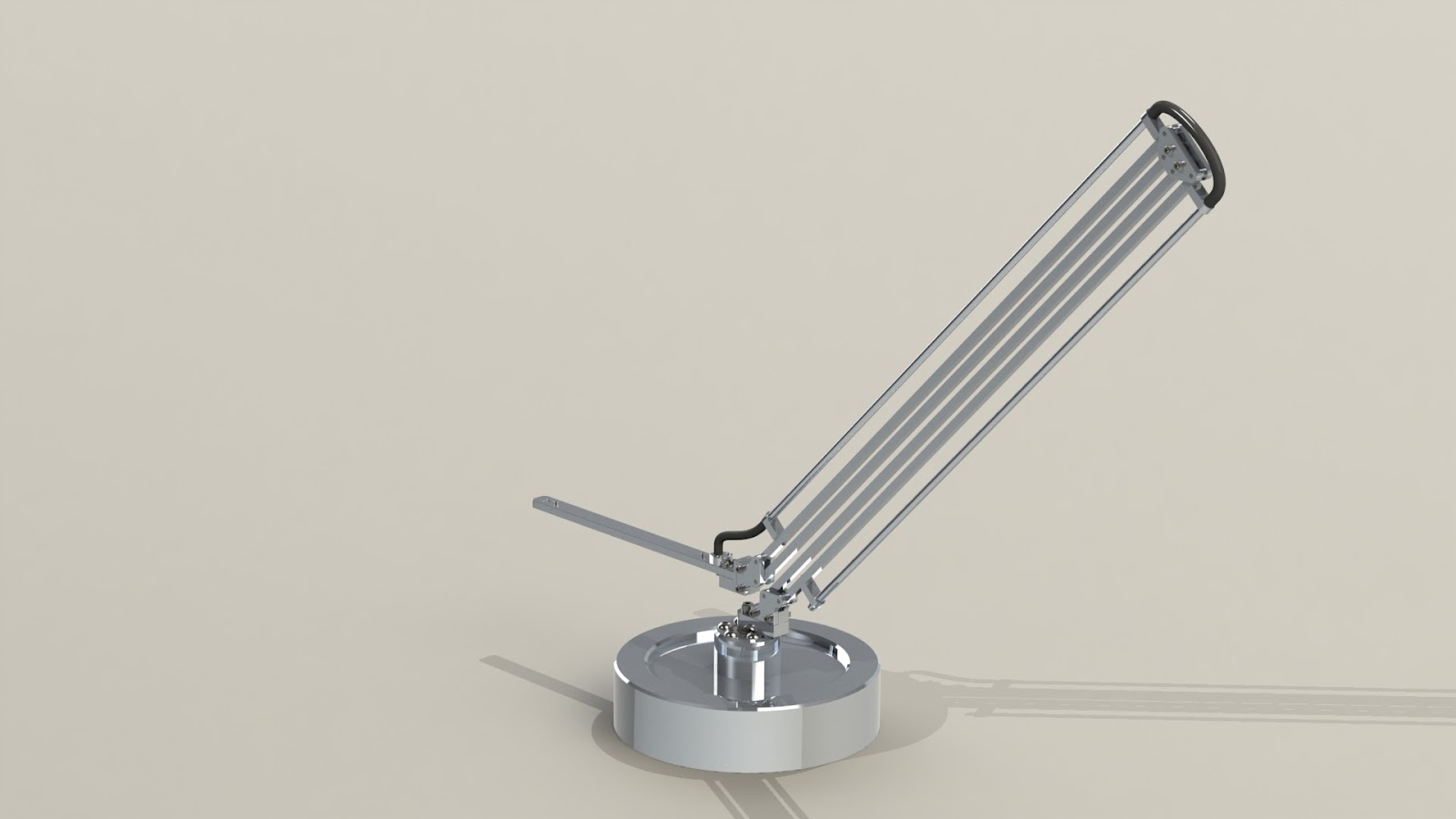
Here's a few quick renders of the lamp in a few positions.


This design has a swivel base to give the lamp more flexibility. The light is held by two parallel arm segments. No matter where the light is positioned it will always be parallel to the base of the lamp. I found a really cool led strip that is a 10 watt LED, so it should easily light up the desk and maybe even the room. I made sure the base was large enough that the lamp would never tip, even when fully extended. The base is an 8" diameter piece of aluminum. The current base will weigh over 9 pounds while the entire arm and light should only weigh a little over a pound.

I started with the arm because the pieces were small and required little material removal. The long pieces used for the parallel arm gave me an excuse to use my 40" calipers (I had been itching to use them to make an actual part).


 These parts could have been made a lot faster if I had a machine that could accept bits larger than 1/8"...
I am fortunate that my CNC mill is very accurate and always seems to hit its dimensions without any need for cutting and measuring, but it's sooooo slow.


All of the arm pieces are made from 1/4" square aluminum. Each one has 1/8" press fit stainless dowel pins.


Each segment of the arm has 1/4" aluminum tubing to keep the wires hidden and protected. The tubing is .035" wall, so it doesn't add much weight at all.


The arm has nearly zero play in the joints. Even the slightest touch to one end will cause the other to move as well. The two end pieces are always perpendicular to each other. It's also symmetrical which makes it harder for me to assemble it incorrectly =D


The arm is held in place by the clamping force from the center joint's plates. This picture also shows the size of the lamp.

So far the lamp seems really solid even though it's made from such tiny aluminum rods. It should be a nice addition to my desk once I finish the base and LED housing.

Monday, August 20, 2012

Guitar Assembly

It's been in this state for over a month. I'm slowly coming to the sad realization that its going to be at least another month before it gets past this point. The good news is that I have it assembled and playing even though I'm missing most of the electronics and most of the pieces that make up the body. The bad news is it's somewhat difficult to hold while playing in it's current state.

The last big piece I needed to make it function was the main body piece. I was very fortunate to get access to a machining center. Always take up opportunities to make parts on a real CNC. The body was 90% machined in 2 setups. One setup to get the top and one to get the bottom. While getting the tool paths generated took some time, the machine time was a few minutes for each side. That's pretty fast considering the amount of material removed. Auto-tool changers and flood coolant really make aluminum parts fast to machine. 


This is one of my favorite set-ups of all time. I had trouble coming up with a good way to run the wiring from the pickups to the electronics area without the need for a large plate to hide the slots for the wires. My best idea was to drill a hole straight through half of the body. I got to use a 12" long .1875" diameter drill bit. It wasn't really any different from using a normal drill bit... I just thought it was cool. Once I get around to finishing the body I'll counter bore the end of the guitar body so the connector will seat cleanly in the end. The end result will be a very clean looking electronics setup, but it isn't what I would call friendly to machine.


Everything bolted together nicely. I chose to run the lightest gauge strings I could find at my local music store.     I strung the guitar over a month ago so I honestly don't remember which size I used. They took a lot less tension than I had expected. The neck can easily handle thicker strings but I figured I would try out some thinner strings and see how they work with the incredibly rigid aluminum construction.


 Alright... It doesn't quite look like a guitar yet, but its getting there. If you only look at the neck you couldn't tell it's incomplete. The main reason for assembling it without all of the pieces, aside from my lack of patience, was to make sure it sounded decent. The all aluminum design is kind of risky. Most guitars are made from wood, which is a dead material. Dead materials make a thud when hit. Aluminum will ring for quite a while when it isn't damped by something like a hand. Tap-testing a number of the guitar parts including the body made deafening rings that lasted for minutes. After assembling everything the guitar became dead. My guess is that it's due to the bolted joints and the dissimilar materials. In any case it doesn't resonate badly.


 One of my favorite parts of this guitar is the string alignment system. I had to align the strings before passing over the nut. My system uses quite a few stainless parts, but it looks pretty cool and seems to provide near-frictionless alignment.


Overall the sound of the guitar so far is pretty amazing. It has a brighter sound to it than my other guitars. My wooden guitars sound muffled. Since this guitar has different pickups, electronics, and strings along with the aluminum construction I don't know what makes the difference. I do know that I like this guitar's sound better than my other guitars. I've been playing it for over a month now and I just can't will myself to play my wooden guitars. The metal neck has some serious mass to it. When playing solos the wooden guitars can't compare. The thinner strings probably contribute to how easy it is to play, but the solid feeling when I press down on the fret board really makes a big difference as well. The wooden guitars just feel light weight and cheap in my hand. The best way to describe the feeling is holding a solid metal product in one hand and a plastic one in the other hand. The metal almost always feels higher quality. I'm sure most people that play a wooden instrument fear that a neck might snap if it's dropped or mistreated. Not with this guitar. If someone were to try to smash a guitar like this at the end of the concert they would be left with a broken stage rather than a broken guitar.

Pros (so far):
-Brighter sound
-Quality feeling
-Easier to play fast (may be due to the strings, but the solid feel definitely helps.)
-Unlikely to break

Cons (so far):
-Hard to hold (it's missing most of its body)
-Lack of adjustability (It currently has one pickup directly wired to the amp. No volume or pickup selection yet.)
-Thermal stability. The guitar has a warm-up period where it goes out of tune until you play it for a bit. The tuning goes sharp as I play, so it can't be the strings slipping. Since the strings are steel and the neck is aluminum, the neck should expand faster than the strings with an increase in temperature. This should put more tension on the strings and raise the pitch. I haven't confirmed this as the reason for the tuning shift, but I can't come up with a better reason given the conditions.

I'm pretty excited to finish this project up and see how others feel it compares to normal guitars.