Showing posts with label CAD. Show all posts

Sunday, November 30, 2014

Servo Spline Adapters

My transmission design for the Mini Combat Robot uses large servo gears. Unfortunately the output from these gears is a spline shaft. I had to come up with a way to easily adapt to the spline without making a sketchy connection with the servo horns that are meant for those servo gears. My first technique for making a servo spline can be done with a milling machine. It's a fairly straight forward and doesn't require special tools.


I put a "blank" shaft into a collet block. The collet block isn't required, however holding a round part vertically in a vise can be difficult to align. It also has a good chance of slipping which could break tools and ruin the part. The first thing I did was drill a set of starter holes. I used a small carbide ball end mill because it was the only tool that could make a mark smaller than the drill bit I wanted to use. Each hole corresponds to one of the teeth in the spline. I designed the holes so the outer edge would meet up with the tip of each spline tooth.


Once I made all of the starter dents, I proceeded to use the final size drill bit. Each hole was very close, but none of the holes intersected. If the holes intersect the drill bit will likely drift and break. The final step was to mill out the center. Milling out the center creates the inner part of the spline. It is important to design the geometry such that the leftover wall between the drilled holes fits between the spline teeth. I simply plunged and endmill down to the desired depth and let it swirl around to the correct diameter. This opened all of the holes drilled to the center.


This is the final shaft. The part fit snugly on the spline and didn't seem to damage the spline even under loading conditions. I used this part on the Mini Combat Robot until a design iteration forced me to a 3D printed design (I no longer had access to a mill). Any mill with CNC or even a digital readout can produce splined holes.


This is a 3D Printed replacement for the metal adapter. I needed a different pulley, but I couldn't use the metal spline shaft for the upgraded design. I decided to 3D print an adapter instead. I used the same geometry as the metal spline and simply printed a new adapter. It also slipped right on and worked first try.


Here is the 3D printed servo adapter as well as a splined shaft that copied the original servo spline. I doubt an FDM type 3D printer could produce the details required for this spline to work, so I'm glad I went with the SLA type 3D printer (Form1+). Making giant servo splines led me to test miniature servo splines.


The first part to my process to make a servo spline is getting a picture of the spline itself. I use this picture and one reference dimension (the outside diameter of the spline) to trace the spline profile. This seems to be pretty reliable and is able to get details that my calipers can't measure.


Here is a screen shot from the CAD I used for the servo spline. I get the spline dimensions by tracing the profile that comes from the drawing. It is surprisingly fast to CAD this way. The camera image reveals a lot of details that my measuring instruments won't capture.


Here is a servo spline made for a micro size servo (9g servo). The printer was able to handle the small details required to make the spline.


The gear fit perfectly onto the servo first try. I attempted to strip the spline, however I only managed to cut myself with the 3D printed gear teeth. I was unable to get the spline to skip on the servo.

For future projects using large servos I will attempt to make more metal shafts and splines. I find them more durable than the 3D printed parts. I also know the servo gears will strip before the metal spline slips. The 3D printed splines for smaller servos are too awesome. I'm still amazed the printer can handle details like that. The cool part is these splines can be put into any 3D printed part. It doesn't matter whether the part is round, square, or even a hexapod leg!

Saturday, November 1, 2014

Quick Project - Evil IronMan

I got invited to a Halloween party about two hours before the party started. The party had a mandatory costume policy. Being an engineer and a new owner of a 3D printer I figured I HAD to 3D print my costume. The first thing that came to mind when thinking of 3D printing and Halloween costumes was an arc reactor. I've seen a bunch made on the internet and even a few for various Halloweens in the past. I remember that I had a box of LEDs. Unfortunately, I discovered that I only had two blue LEDs. Luckily I also had eight red LEDs... so the obvious costume became evil IronMan. I spent about 30 minutes drawing up the part in SolidWorks and then sent it to the printer. The print time was a little under two hours (it's cool to be slightly late to parties). While the part was printing I had to make the wiring.


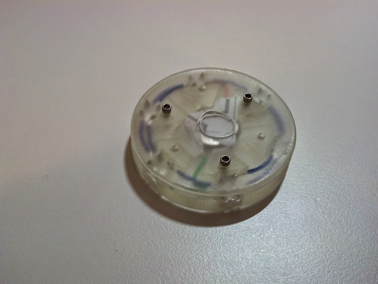
I pushed each of the LEDs through a 1:1 drawing of the frame. I soldered all of the LEDs together with some solid wire to give some structure to the electronics. I also used two bent spiral wires for the + and - connections to the battery. I tore away the paper to release the electronics for the final assembly. I didn't use any current limiting resistors or a proper current driver because the battery voltage was lower than the rated voltage for the LEDs. I also figured that the small coin cell battery wouldn't be able to supply enough current to fry six LEDs in parallel.


Here's a top side view of the arc reactor. Each of the LEDs stuck out from the frame to ensure maximum brightness. It also saved some material and print time.


This is the back side of the arc reactor. I have paper shoved between the battery and the contact to prevent the LEDs from turning on. I didn't have a switch so the back has to be unscrewed to connect and disconnect the battery.


This is the arc reactor shining through my shirt. The camera doesn't do a very good job showing how bright the LEDs looked shining through my shirt. I used lots of tape to hold it in place.

Surprisingly the arc reactor stayed lit up all night. I didn't even have to break out the spare battery and hex key that I kept in my pocket. The design wasn't too great, but im pretty proud of it considering it went from concept to finished product in a little over two hours!

Saturday, October 25, 2014

New Machine - Form1+ 3D Printer

After thinking it over for a few months I decided the usual FDM type 3D printer I was building (the kind that squirts out plastic like a hot glue gun) wasn't going to meet my needs. I just moved and no longer have access to mills, lathes, or other metal working equipment aside from my trusty file and hand drill. I decided a 3D printer was the only way to continue my projects without making a mess in my apartment. After looking around at the different available 3D printers I came across the Formlabs Form1+ printer. This printer uses SLA technology. SLA printers use a photosensitive resin that solidifies when exposed to a light source. The resin in this printer cures with a UV laser.

I need a printer than can make parts with fine details, high accuracy, and decent strength. Although I'd love a printer that could make metal parts, however I'm a few orders of magnitude away from being able to afford one. I decided to settle with a printer that makes plastic parts. The FDM printers (like the one I am/was building) are nice because they have become very popular. The popularity has driven down the material costs which makes the printers very affordable. There is also a large number of users who have lots of great tips and tricks for getting high quality parts. Unfortunately the nozzle design in an FDM pritner limits the minimum features size. The fusion of layers through heat also tends to leave voids which causes very different properties depending on a part's orientation in the printer. This can make "engineering" grade parts difficult to make.

The SLA printers have only recently become available to hobbyists, so there is not a very large number of users. The material is somewhat proprietary, so it costs 3-5 times more than an FDM printer for a given volume of material. The quality from the SLA printers can't be beat by the FDM printers. The laser curing technique is able to make much finer details in the parts. I expect to be printing gears that are 32 and maybe even 64 pitch. The parts are also solid, so the material properties are going to be the same regardless of the part orientation. There should also be fewer voids in the parts, which will make "engineering" grade parts easier to produce.


Here's the printer in all its glory. I personally find the printer aesthetically pleasing. It also fits well on my bookshelf.


Here's the setup for my first prints. These parts are shock spring mount replacements for my rc car. The original ones no longer fit properly due to my machined replacement parts not being the exact same geometry as the original components.


The printer readout is pretty cool. It tells me the remaining print time and the number of completed layers. The remaining time is exact and can help me schedule my time around the printer so I can be as productive as possible.


This printer is upside down compared to FDM printers. The table rises out of the resin to grow the parts. It's a pretty neat concept and seems to work well.


Here are the final parts after removing the excess resin with isopropyl alcohol. They came out perfectly first try. I'm sure more complicated parts or parts with tighter tolerances will require some test parts, but parts like these take nearly zero effort to make.

Overall I'm pretty happy with the printer. I have more project ideas than ever now that I can make parts without labor. I'll be running test parts for things like gears and press-fits. For now I'm not going to finish the 3D printer I started making. The FDM printers can't make the parts I want to make. It is a good XYZ CNC platform, so I should be able to use it for another project some time in the future.

Friday, August 31, 2012

Desk Lamp - New Project

During my last semester at school I discovered the need for a desk lamp. The one I used during the semester was chunky and didn't quite have the reach I needed to light the center of my desk (I put the lamp's base on one of my speakers). I also burned myself a few times on the light housing. As usual I figured I could do better.

These were a few of my design thoughts:

-High power LED (More light, less heat, nearly unlimited lifetime, less power consumption, smaller, lighter)
-LARGE (My computer setup is around 80" wide)
-Light weight (The lighter the arm is, the smaller the base can be without the lamp tipping)
-Cool looking (who wants an eye sore on their desk?)

I actually came up with this a few months ago, but I hadn't decided to make it until the past couple days.

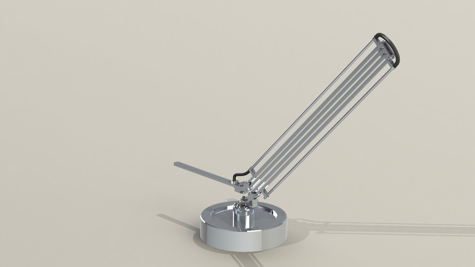
Here's a few quick renders of the lamp in a few positions.


This design has a swivel base to give the lamp more flexibility. The light is held by two parallel arm segments. No matter where the light is positioned it will always be parallel to the base of the lamp. I found a really cool led strip that is a 10 watt LED, so it should easily light up the desk and maybe even the room. I made sure the base was large enough that the lamp would never tip, even when fully extended. The base is an 8" diameter piece of aluminum. The current base will weigh over 9 pounds while the entire arm and light should only weigh a little over a pound.

I started with the arm because the pieces were small and required little material removal. The long pieces used for the parallel arm gave me an excuse to use my 40" calipers (I had been itching to use them to make an actual part).


 These parts could have been made a lot faster if I had a machine that could accept bits larger than 1/8"...
I am fortunate that my CNC mill is very accurate and always seems to hit its dimensions without any need for cutting and measuring, but it's sooooo slow.


All of the arm pieces are made from 1/4" square aluminum. Each one has 1/8" press fit stainless dowel pins.


Each segment of the arm has 1/4" aluminum tubing to keep the wires hidden and protected. The tubing is .035" wall, so it doesn't add much weight at all.


The arm has nearly zero play in the joints. Even the slightest touch to one end will cause the other to move as well. The two end pieces are always perpendicular to each other. It's also symmetrical which makes it harder for me to assemble it incorrectly =D


The arm is held in place by the clamping force from the center joint's plates. This picture also shows the size of the lamp.

So far the lamp seems really solid even though it's made from such tiny aluminum rods. It should be a nice addition to my desk once I finish the base and LED housing.

Wednesday, June 13, 2012

Guitar Bridge

I finished the bridge on the guitar! I actually started it last summer when I made the string adjusters and half of one of the parts that makes up the base. I made most of the base at school but still had to complete the half finished part. It took me less than an hour to pop it out (including writing the code which is done by hand rather than with a CAM program). 


I also have a new phone so the camera is less blurry (mostly because it doesn't lag while taking pictures).

I also finished up some more of the head last week.
 I had reverse-engineered some tuning knobs into my CAD from a drawing that I had found online. When I went to one of the guitar stores I found the EXACT same ones I had found online. I had to buy them once I realized that. It saved me a ton of time when designing the head.
The head turned out pretty nice. It still needs the string alignment posts.  I have the material for those turned down to the right diameter, but I still have to cut them to length. Ill finish those when I get bored milling and want to switch to running the lathe.


 I also got a new set of calipers. They're a bit bigger than my old 6" set. You can really only make parts as accurately as you can measure them, so I figured it would be good to get a HUGE (40") set of calipers to make those giant parts to within 0.001 inches. It looks like my neck is about 0.001-0.002" over 19". I'd say that's pretty good considering I had no way to check the dimensions of my part as I was machining it.


The guitar is slowly coming along. If I finish the main piece for the body I'll basically have it in a playable state. I hope the resonance of the aluminum gives it a unique sound, but doesn't make it sound awful. I do have some plans to add damping material into the neck if the resonance makes it sound strange.

Wednesday, February 22, 2012

Light Saber - New Project

I have to stop coming up with projects...
Anyways. This one is more of a machining exercise than a design project. I wanted to test some new tooling and machining techniques on the CNC lathe at school. This is the first real project I'll have tackled on a CNC lathe before, so this should be a great adventure.

The idea for the light saber is that it has to feel as "real" as possible. (Yes I know real and light saber contradict each other, but I wanted to make something Obi-Wan might pickup by accident.


I tried to keep the center of gravity on the hilt. That way it might behave as if the blade were made of light. Since I didn't even attempt to invent something that actually performs like a light saber I figured polycarbonate tubing would be adequate for the blade. This way I can actually hit things and the blade probably won't shatter. I threw in some gears at the top because I thought it looked cool and I have some leftover stock from machining a few parts for someone. The "power source" will remain a secret until I verify it works.

Sunday, January 15, 2012

Guitar - New Project


Hey! It's a new project. Ok... I lied. I sorta played around with designing a guitar over a year ago. However I didn't get serious about it until now. I made a few pieces last summer to test a new vice I bought for my CNC.

I attempted to make the bridge for the guitar. The aluminum adjustment pieces turned out great. The prototype plastic bridge machined fine (except for a minor code error that cut through one corner). I didn't like the feel of the bridge, so I redesigned it. I probably won't be able to make any parts for a while until I get access to the large new CNC machines at school. 

Here's a few renders of different revisions of the guitar design:


The evolution of the design has made the parts machinable and the material affordable because I no longer need a 300 dollar billet of aluminum to make the body. The lightening pattern not only makes it look better in my opinion but it also drops the weight down to a normal-ish guitar. Oh... I'm not sure if I pointed out that the thing will be entirely made from metal. The majority will be aluminum, while the fret board and screws are stainless. I figured a stainless steel fret board would scratch less easily than an aluminum one.

Some key features to this current design are:
- Countersunk hex socket screws for fret markers. They also hold the fret board to the neck.
- A 3D profile machined neck.
- Interchangeable parts. If I decide the design sucks after I make the guitar, I only need to change some of the parts. The design is split into many different parts that bolt together, so I can always replace parts that don't perform the way I want them to perform or if they get damaged.

Hopefully I'll get this project machined in a timely manner unlike the long board.

Saturday, December 17, 2011

Black Friday Computer Upgrade

I had an EXCELLENT Black Friday. I didn't want to distract myself for the last few weeks of school, so I shipped my amazing find home instead. In the end my Black Friday deal turned out to be a great "survived" the semester gift. This became one of my few impulse buys. I saw the deal on Newegg and couldn't resist. Who wouldn't want three monitors?

 They work great for CAD. Those wide format assemblies like my long board can be put 1:1 on the screens.

Ok... I'll admit they are somewhat ridiculous, but they finally gave me my "Command Center". I had been running two monitors for a few years before getting these new monitors. I found I have trouble using a computer with fewer than 2 monitors. I usually put whatever program I'm using on my main screen and something I need to use often on the other. When designing stuff I put my CAD on one display and the file browser on the other. I never have to minimize the CAD in order to open new files. With the three monitors I use the center and right monitors as I always have. The new left monitor gets used for "research". Research is usually Google for whatever information I might need for designs or homework.

Now I just need to figure out how to fit the monitors and my rather large speakers on my small desk at school... I'll probably have to hang a bit over onto my roommate's desk. Hopefully there won't be too many complaints =D

Thursday, June 30, 2011

Long Board - New Project

After a year of walking to class I decided I needed a long board to get to class. In my usual style I figured I should make one instead of buying one. I started by doing some research on the designs and standards for long boards and skate boards. I saw a number of different truck designs that seemed common. It seems that the rubber bushing style of truck is the most popular. In this design the truck is forced to straighten itself out by squished pieces of rubber. These pieces give the boarder more resistance as they attempt to steer the board. My personal favorite design used metal springs instead of the rubber bushings. I like to design things to last. I figured the springs would never deteriorate with time. Unfortunately I couldn't figure out how to make the trucks small and use the springs. Eventually I decided to go with the standard design for long board trucks. The one thing that really bugged me about this truck design was there wasn't a defined mechanism that caused the truck to turn. The pins in the trucks relied on a loose fit in order to actually turn. I started to look for an improvement when I stumbled upon spherical bearings on Mcmaster. These bearings gave freedom in all directions, which was the exact motion I needed. I designed the trucks around these bearings.  The spherical bearings give the trucks fully defined motion.

After deciding on the components I immediately started up SolidWorks and started poking around with different designs. Eventually I settled with this design for the trucks.
This render of the entire board has an older design for the trucks. I spent a few days changing around the design to make it easier for me to machine. The best looking board in my opinion was one made from 1/2" polycarbonate. I figure this board will really stand out when around the regular long boards.
I split the truck into many different pieces to avoid material removal. The biggest limiting factor when I'm machining is removing material. Splitting up pieces meant a large portion of the parts were extruded aluminum with holes drilled in them. Parts like that are really easy to produce with a manual machine. The design also meant that I only needed CNC work for the bearing seats and the side plates for the trucks. I attempted to locate the parts by geometry instead of the bolt holes themselves. The most critical surfaces required parallel edges, which are very easy to produce in one setup on either the manual or CNC mill. The only new thing for me on these trucks was the use of spherical bearings. I hope they perform as well as I imagined them performing.

Saturday, January 8, 2011

Powered Desk Chair

This project had a lot of potential, but I kind of let it fail. Maybe I'll finish it one day, but it probably won't be any time in the near future.

I had an Ikea desk chair that didn't roll very well, so I figured I'd modify it into a powered desk chair. It would have "swerve modules" to give it the ability to strafe and turn just like a normal unpowered desk chair. The design was fairly simple stuff that I had basically done in robotics at my high school. The intended final chair would have looked like this, but the electronics required to make it run properly were a bit out of my budget range.

The continuous 40A motor controllers put the electronics out of my budget considering the ones I had used in the past cost around 90 dollars a piece. I made the three swerve modules before I decided to ditch the project.

 As with most of my projects I had to use the arbor press. It took apart that Ikea chair with ease.


Even though I bagged the project I learned a lot from its construction. In order to make the sprockets I wrote a program in python to generate the g-code for my CNC to cut any size sprocket. I also learned what tolerances are needed to make a chain drive without a chain tensioner and I also learned what tolerances work with bevel gears. Did I mention that I also have 3 very cool looking paper weights?

Sunday, August 15, 2010

Phone Case - New Project

My phone was a little bit too bland for me, so I decided it needed a cool case. I couldn't find one that I liked for it, so making one in the shop was the next best option. A few years ago I had designed a case for my IPod, but I never got around to machining it because it required me to write too much code for my CNC.
It was made from 2 pieces. The front plate was simple and could all be machined in one setup, but the back piece need to have the center machined out. Aside from the time required to write out the tool paths by hand, the machine time on my CNC would have been too unbearable for me to make the case. This did however serve as the basis for my phone case concept.

I started off designing the phone case by getting the dimensions for my phone. Thankfully it wasn't one of those "ergonomically" shaped phones, so the phone was basically a rectangle with rounded corners. After taking down the dimensions I opened up SolidWorks and started playing around with different concepts. Eventually I came to this design.
The general concept was a ring that surrounded the phone and a plate on the top and bottom that held the phone in place. The ring only requried a slot to be machined around the inside perimeter. This would leave a nice little plug of material in the center that could be used for another project. This case needed #0-80 screws. Since the sides were so thick the case needed button extenders to allow me to actually use the phone. For some reason my first thought was to machine small holes in the side of the case for the buttons to slip into.  This design quickly turned my simple ring idea into a nasty 4 sided machining job. I don't have an edge finder for my CNC, so I was not in the mood to re-zero it multiple times on a single part. With ease of machining in mind I redesigned the case again.
(This render came after making the case. I got lazy and used polycarbonate instead of an aluminum ring as I had originally Intended)

This new design gave me the option to do all of the parts with single sided machining and minimal material removal. Both are things I strongly prefer when producing any part. Hopefully the case will be a quick one day project.