Showing posts with label Electronics. Show all posts

Sunday, February 1, 2015

New Project (Finished too) - Computer Charger Repair

The output wire from my laptop charger frayed and shorted about a year ago. The wire was built into the charger and broke right where it came out of the charger. I couldn't do without my laptop so I had to get a new charger. I kept the broken one so I could repair it and have a spare at some point. There wasn't enough wire left out of the charger to simply solder the cable back together, so I knew it would need a full case replacement. I also wanted to add a second connector so I could remove the output cable and a similar break in the future.

The charger appeared to be one solid piece of plastic. There were no seams or obvious places to try prying the charger apart. I managed to chip away the rubber that sealed the output cable to the charger. The small opening let me look inside and determine the wall thickness of the charger's case. I could also see the orientation of some of the internal components. I guessed the circuit board was inserted right-side-up into the charger during assembly which led me to guess which side was the lid.


I used a mill to cut away just the outer wall of the charger. I stepped down a small amount with each pass until the top lid broke free. It turned out to be held in with plastic snaps. I believe the lid was glued or friction welded to the rest of the case. It was a clean, but unrepairable design. I managed to avoid cutting any of the components.


The charger had pretty simple internal geometry. I reversed engineered the critical geometry in the case to hold the remaining components.


I bought a pretty nice looking connector without looking at the dimensions... The connector wasn't going to fit in the original case geometry, so I was forced to put it on the lid. I'll admit its a strange form for a charger, but it worked out. I originally planed to use the black resin on my 3D printer to make it look nice, but I got lazy and used the clear resin that was already in my printer.


Here is the main part of the case after it came out of the 3D printer. This is probably the largest part I've printed so far. Thankfully it didn't have a print failure like I had with a few other parts recently.


The lid also printed cleanly. As usual the extra material for the support felt like a waste, but there isn't much I can do to avoid adding it.


I wanted the charger to be symmetrical, so I put screws on the bottom. They don't hold anything together, but they do look nice.


The charger fit snugly into the case. The wall power plug even fit into the case!


Here's the lid before squishing the remaining wires into the charger.


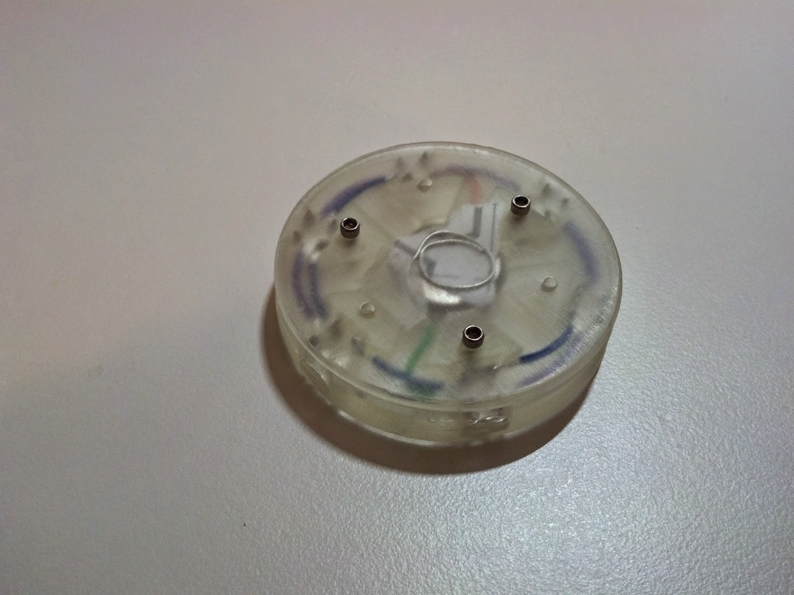
The charger has been revived! The design is pretty strange, but it's functional which is what counts. The upward angle output plug is actually nice because it reduces wire stress when reaching from the floor to a table. It also makes the USB charging port easier to access. I should have been less lazy and printed the charger case in black, but at least the insides are visible like one of the old clear gameboys.


Friday, January 9, 2015

New Project - Cheap Hexapod

I've always wanted to build a Hexapod. They look pretty cool with all of the legs moving in sync. They can also be used as a desktop toy, unlike my RC car, which is basically an outside only toy. The biggest problem with hexapods is they are really expensive. A proper hexapod requires three degrees of freedom for each leg. This ensures that the leg doesn't need to slide on the ground. The three degrees of freedom per leg and six legs require a hexapod to have at least 18 servos. The servo cost adds up fast and had previously discouraged me from building a hexapod. Recently I came across micro sized servos (HXT900 9g servos). These servos cost about three dollars each. Even with 18 servos that still isn't too expensive compared to typical on brand servos that cost about 20 dollars each.

I wanted to build the hexapod around my new 3D printer. The first thing I decided to do was integrate the servo splines into the legs themselves. After a number of test prints I was able to confirm it is possible to create micro size servo splines with my 3D printer (Form1+). I also wanted to keep the design minimalistic and avoid over complicated joints and leg segments.


I bought three servos before I committed to building the hexapod. I printed and assembled one leg to ensure the servos would be strong enough to drive the leg. I also wanted to test the tolerances on the servo splines with multiple servos. This image shows the leg prototype, The only change I made to the leg design was an increase in the depth of my logo.


This was the first "production" run for my 3D printer. I had to make six copies of each leg part as well as the body section. Aside from one print failure (on the main body servo mount plate) everything printed perfectly. I literally couldn't make these parts through machining given the orientations of the splines and the shapes of the parts.


This is the body piece ( the one that printed correctly) as it came off of the printer. There was an update to the printer software that dramatically reduced the material wasted in the support structure for the parts.


Here is the part before support material removal. The supports are removed with wire cutters and then the remaining bumps on the part surface are removed with a file.


The final part looks pretty clean. All of the dimensions seem to be within tolerance for the hexapod. There is some warpage in the part that occurred after the post curing, but it shouldn't prevent the part from being usable.


Each servo requires two 2-56 screws to be threaded into the frame. My hand got pretty tired trying to screw all of the servos into the mounting plate. Each servo fit nicely into the plate.


I decided to try fitting all of the pivots into the lower central support plate. It was fun getting to see the hexapod come together.


This was the first time the hexapod was fully assembled. I knew the wiring would be an issue, but I didn't realize how messy the hexapod would look without proper wire management.


Here is my programming testing setup. I was at my house for the winter break and no longer had access to my 3D printer. I had CNC access but I didn't particularly want to get covered in chips as I usually do when machining. I used a raspberry pi model a+ as the controller. This raspberry pi is the smallest one currently available. I wanted to run the hexpod with linux and python because it makes the programming easier. The hexpod currently connects to a computer over wifi which was really easy to do and should be a convenient way to control the hexapod. The two blue boards are PWM driver boards from adafruit. Each board can drive up to 16 servos ( I needed to drive 18 so I had to get the second board). The boards are controlled with an I2C interface. This means I need a minimal number of pins from the raspberry pi to control all of the servos. It helps to keep the wiring from being a mess.


Here is an early motion test. I programmed the legs to look like they were walking. I still needed to calibrate each servo and complete the actual leg motion program. This shows the hexapod moving its legs near the peak servo speed.


This was the first PCB I milled on a proper milling machine. I've always had access to a dedicated PCB mill, so coming up with my own milling procedure was fun. I drew the circuit board in SolidWorks so it would be easy to generate the G-Code for the CNC. A proper circuit CAD program like eagle probably would have been a better choice.


The PCB I milled was for the hexapod's power supply. This supply is capable of driving up to 20A at 5.5V. I wanted to drive the hexapod with a 7V battery, but the servos and raspberry pi wanted 5V. Each servo doesn't draw very much current, however the combination of all 18 which could all be running at full torque at one time would overwhelm most power supplies. I decided to go with the 20A supply to ensure there would never be a sever voltage drop that could shut down the raspberry pi.


Here is the final hexapod assembly. I ended up milling three plates from polycarbonate to create the electronics mount. The electronics are all held in with zip ties. I would have used screws, but I didn't want to make the standoffs required to mount the electronics with screws.

Unfortunately during testing I managed to break three servos. Shipping the hexapod back from break caused another four servos to die. All of the servos broke at the same internal gear. I haven't been able to finalize testing my leg motion code without a fully functioning set of legs . I chose not to use an existing set of code for the legs because I was excited to create my own algorithm from scratch. I need to rethink my servo choice and look into getting slightly more robust servos. Currently I am looking at using metal gear servos that are around five dollars each. I'm sure the hexapod will be up and running quickly once the new servos are integrated into the design.

Saturday, November 29, 2014

Mini Combat Robot Update... again

I decided to use my new 3D printer to solve any engineering problems with the mini combat robot. The first problem was making the motor controllers fit in the space I left for them.


Here is the motor controller mount as it came from the 3D printer. The part wasted a lot of material in the supports. I designed the part to fit the motor controllers perfectly into the robot frame. This part might be machinable, but I would avoid making this part if I didn't have a 3D printer.


The new motor controller mount allows me to fit the wires in to the available space. It may look messy, but I'm just happy I could make the motor controllers fit into the frame. I knew the motor controllers would fit into the frame, but I didn't account for the wires or connectors. These left the space a bit too cramped to properly mount any of the components. The new 3D printed mount allows me to securely mount the controllers without risking damage during combat matches.


The robot looks pretty slick. I was able to replace the old 3D printed parts either with properly machined components or parts printed with my new 3D printer.


This underside view of the robot shows how the motor controller fits into the robot. I still need to replace the top and bottom plates with real armor instead of thin acryllic.

I didn''t quite mange to finish the robot before losing machine shop access. I've been able to replace most of the poorly 3D printed parts with either higher quality plastic components or metal components, however there is still a fair amount left to finish the robot. The biggest thing the robot needs is a spinner.

Saturday, November 1, 2014

Quick Project - Evil IronMan

I got invited to a Halloween party about two hours before the party started. The party had a mandatory costume policy. Being an engineer and a new owner of a 3D printer I figured I HAD to 3D print my costume. The first thing that came to mind when thinking of 3D printing and Halloween costumes was an arc reactor. I've seen a bunch made on the internet and even a few for various Halloweens in the past. I remember that I had a box of LEDs. Unfortunately, I discovered that I only had two blue LEDs. Luckily I also had eight red LEDs... so the obvious costume became evil IronMan. I spent about 30 minutes drawing up the part in SolidWorks and then sent it to the printer. The print time was a little under two hours (it's cool to be slightly late to parties). While the part was printing I had to make the wiring.


I pushed each of the LEDs through a 1:1 drawing of the frame. I soldered all of the LEDs together with some solid wire to give some structure to the electronics. I also used two bent spiral wires for the + and - connections to the battery. I tore away the paper to release the electronics for the final assembly. I didn't use any current limiting resistors or a proper current driver because the battery voltage was lower than the rated voltage for the LEDs. I also figured that the small coin cell battery wouldn't be able to supply enough current to fry six LEDs in parallel.


Here's a top side view of the arc reactor. Each of the LEDs stuck out from the frame to ensure maximum brightness. It also saved some material and print time.


This is the back side of the arc reactor. I have paper shoved between the battery and the contact to prevent the LEDs from turning on. I didn't have a switch so the back has to be unscrewed to connect and disconnect the battery.


This is the arc reactor shining through my shirt. The camera doesn't do a very good job showing how bright the LEDs looked shining through my shirt. I used lots of tape to hold it in place.

Surprisingly the arc reactor stayed lit up all night. I didn't even have to break out the spare battery and hex key that I kept in my pocket. The design wasn't too great, but im pretty proud of it considering it went from concept to finished product in a little over two hours!

Saturday, December 14, 2013

New Project - 3D Printer

I decided to make a 3D printer. 3D printing seems to be the wave of the future for producing many parts. There are a few different types of 3D printers, one of which, the extrusion type, seems to be the most popular on the market. This kind of 3D printer takes in filament, which is essentially plastic wire, and extrudes it into a small bead of plastic. The printer moves the extrusion nozzle on a table to draw a part. This printer is basically a fancy hot-glue gun that makes 3D shapes. 

The consumer grade 3D printers on the market are pretty slow and they don't produce the best quality parts. In addition, most of them don't use support material. Support material is a second material used by the 3D printer with the standard plastic. The support material can be dissolved so you can make parts with overhangs or other features that require additional support.

The concept for this 3D printer is to use high power hobby brushless motors, similar in size and power to those used in the heavy weight combat robot I built last semester. These motors aren't meant to be used as servos, so the printer needs custom motor controllers as well as additional hardware to properly drive the motors.

The brushless motors have 3 wires: phases A, B, and C. Brushless motors have magnetic coils in multiples of 3, one set for each of the 3 phases. These coils are connected together in a few different configurations, such as wye or delta, which provide different characteristics to the motor. Driving the motor is the same regardless of the coil configuration. Phases A, B, and C must be pulled to supply voltage, ground, or floated to make the motor rotate. A nice resource for this would be AN857 from Microchip. Microchip makes microprocessors, transistors, and other components used in motor controllers. AN857 is one of their application notes on brushless motor control.

Most hobby brushless motors are sensorless, so there is nothing added to the motor to help a controller determine when to switch which phases are being powered. Since a servo needs an encoder, I decided to use this to perform the commutation, or timing for when the motor controller switches which coils are powered.


Here's a picture of the custom motor controller. This board uses power MOSFETs. MOSFETs are a type of transistor that is great for high frequency switching applications. There are 3 pairs of power MOSFETs; each pair corresponds to one of the motor's phases. One MOSFET in each pair is connected to the power line, and the other in each pair is connected to the ground line. If a high-side MOSFET is on, that phase will be connected to the power line. If a low-side MOSFET is on, that phase will be connected to ground. If neither is on, the phase will be disconnected from power and ground. If bot MOSFETs are on, power fill flow from the power line to ground. In this case the MOSFETs will form a short circuit. With a large power source, batteries or computer power supply, the MOSFETs will fry from too much current.

Portions of this project became a group effort for final projects in two of my electronics classes. The motor controller and its design are part of an advanced electronics course. The logic portion of the control, which is built on an FPGA and microprocessor board is part of a digital electronics and embedded systems course.

The logic portion of the motor controller is implemented on an FPGA. This includes PID control, which is being temporarily used until the mechanical portion is built; motor commutation; and coordinate input. An FPGA is a chip that has programmable logic gates. An FPGA allows the user to implement hardware design on the chip. Certain features like encoder counting, and motor commutation are very convenient to implement on an FPGA. Since these features are in hardware, certain situations can be made impossible. One example of this would be short circuiting two of the MOSFETs together.


Here is a quick video of the motor. The motor controller is connected to a variable voltage supply. The motor controller is just switching which phases are powered depending on where the motor is positioned. The voltage determines the peak speed of the motor. I can't remember if this test went up to 12,000 rpm, but the motor and encoder functioned up to this rpm.


This shows the output of the encoder at 12,000 RPM. The signal is very clean. There are two square waves because this encoder is a quadrature encoder. There are two sensors, 90 degrees out of phase from each other, which read lines on the encoder. This lets the controller decode a resolution four times higher than the line count on the encoder. This encoder can be read at up to 8192 counts per rotation.

The mechanics for this project are meant to be relatively cheap to make. Linear slides in the gantry are built using hardened round rails and ball bearing bushings. These components are commonly used in other 3D printers and can be found very cheaply on sites like Ebay. The design for the printer isn't completely finished. There table motion system and mount, material mount, extruder, and heater block have yet to be designed. Thankfully the project proposed for class only required the motor controller, not the full 3D printer. I will likely finish these parts over the winter break when I have more free time.


Here's a screen shot of the CAD in the 3D printer's current state. The gantry design is done and looks pretty sweet. The table still needs some work, and the extruder doesn't exist.


These are the bearing blocks used in the gantry. Each one holds a round rod ball bearing bushing. The bushings are tight slip fits, so you can put them in by hand, but it does require some force to push though. Each of the bushings are held in with snap rings. Most of the dimensions on this printer are a mix of english and metric units. Linear slides are all metric, but screws and part dimensions are english. I wanted to use existing stock and screws for most of this project to keep my costs lower, otherwise I would have made every dimension metric.


Here are most of the components in the gantry. Locating dowel pins are not pressed into the bearing blocks or the blocks that hold the X axis rails.


The frame is made from MDF. MDF was chosen because it is pretty cheap, it cuts nicely on a CNC router, it is relatively dense, and it doesn't produce splinters like other woods. If I get around to paining the frame it will look even cleaner than it does now.


Eventually I will glue the frame together, but for now it's going to be held together with clamps. There are still a few features that need to be cut into the frame, so I want to be able to replace or modify the 6 panels.


 Here is the servo mount. The motor is a 350KV outrunner motor that should be able to output 1200 watts. This is total overkill for the printer. This size motor is used because of the low KV which makes it easier to control at a particular voltage. It also eliminates the need for a gear box, which can introduce backlash to a system. The encoder is mounted on top. The gantry uses an H-Bot design. This design uses one loop of belt within the gantry. The servos can be stationary and mounted to the frame with this design. This makes the gantry much lighter than a traditional gantry design where each motor separately controls each axis. In the H-Bot design the position of the gantry is a linear combination of the two motor positions. The gantry moves in the X axis when both motors spin the same direction. The gantry moves in the Y axis when both motors spin in opposite directions. If only one motor is spun, the gantry moves equally in both the X and Y directions.


 Here is the FPGA board and motor control board wired up to the system for testing. The final system will be wired in a much cleaner way...

I'll try to keep up to date on the progress over break. I have this and a number of other projects to start and complete, so I should post more often than during this semester.